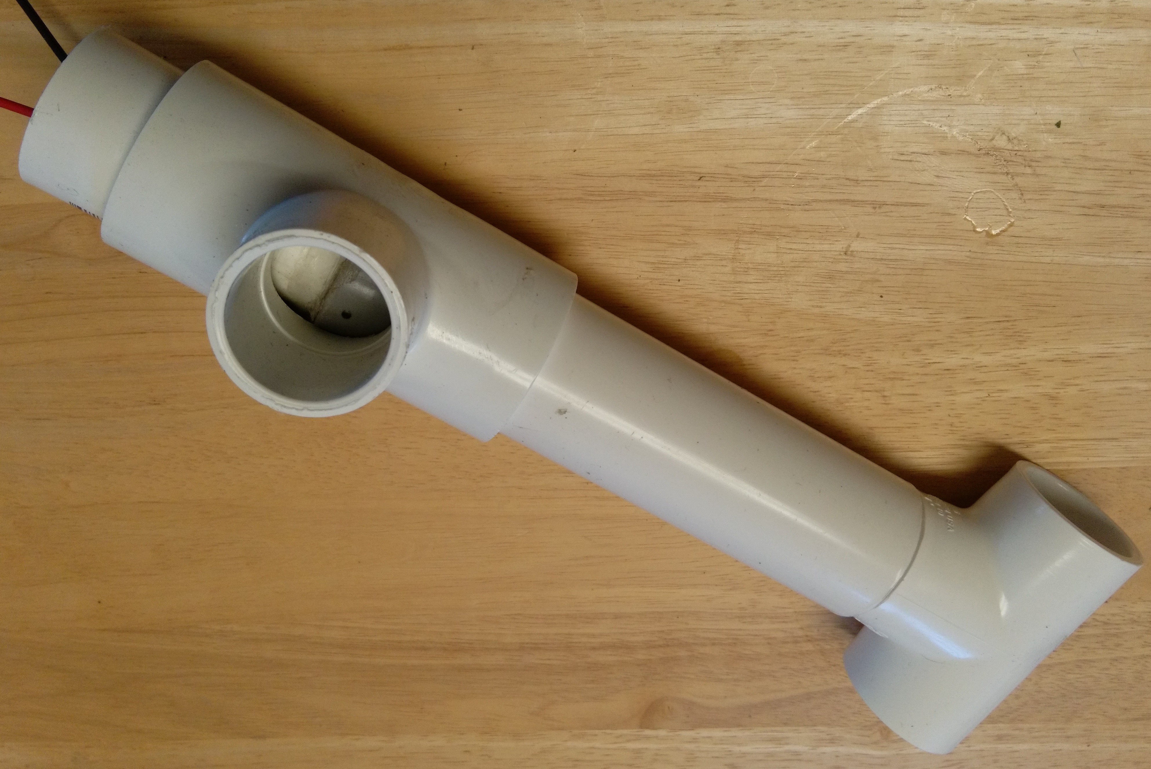
Here is the latest rotor (I've added another coupler and section of pipe to extend the T on the actual rack, I should have made the top pipe longer, but I can adjust it later)
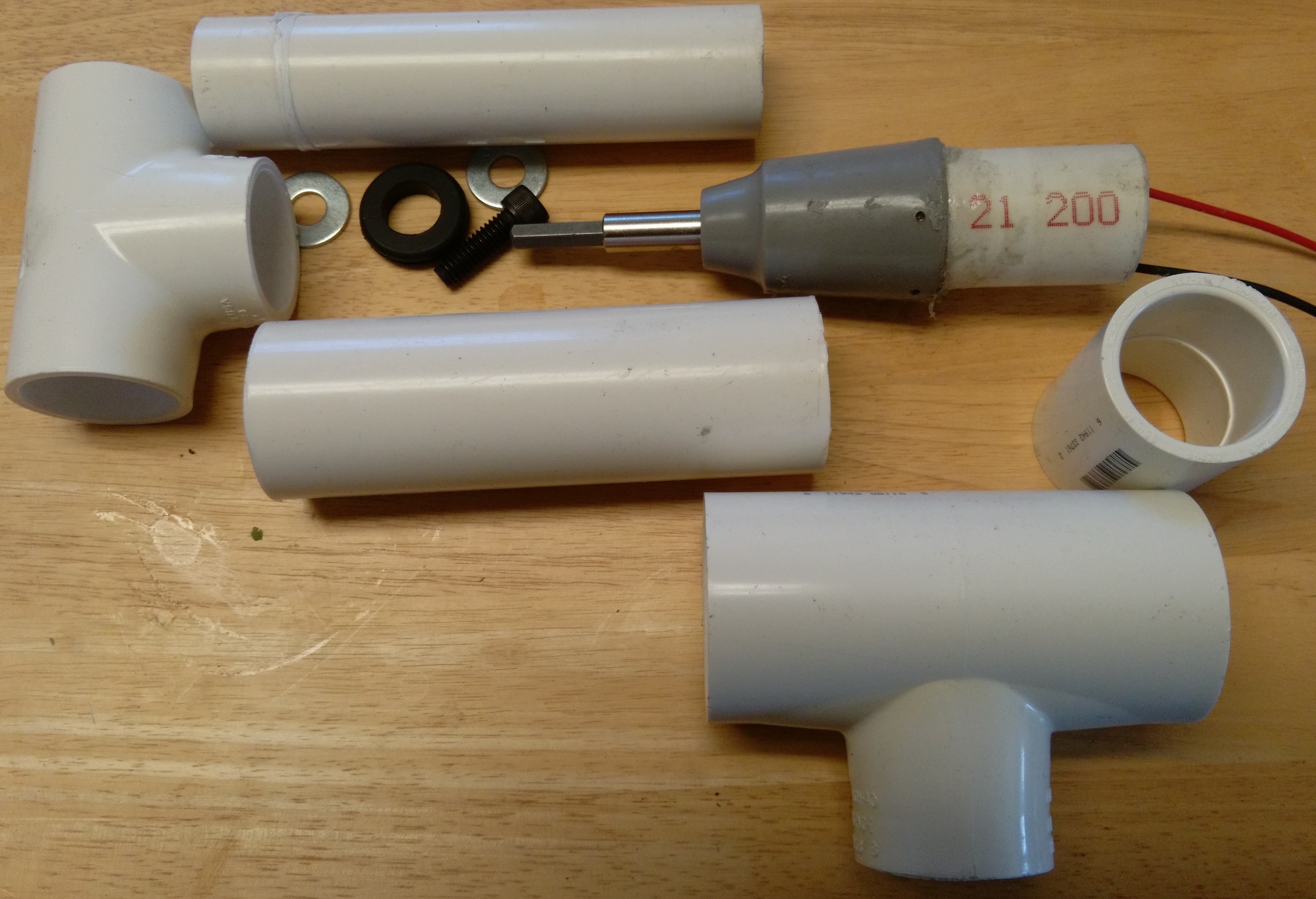
The first pic shows most things broken out vertically but where they end up horizontally in the final assembly.
The motor is inside the thin walled "21 200" piece and is glued inside, and the pipe glued to the gear housing. That piece goes into the coupler on the right. The gear housing fits inside the larger T at the bottom (1-1/4 thru, 1 side) to the middle (bottom pic). The 1-1/4 tube holds the motor in from the left side, and the motor-cork goes inside the smaller and slightly longer pipe (fits into the 1" T or a coupler) which goes all the way to lightly sit on the motor housing.
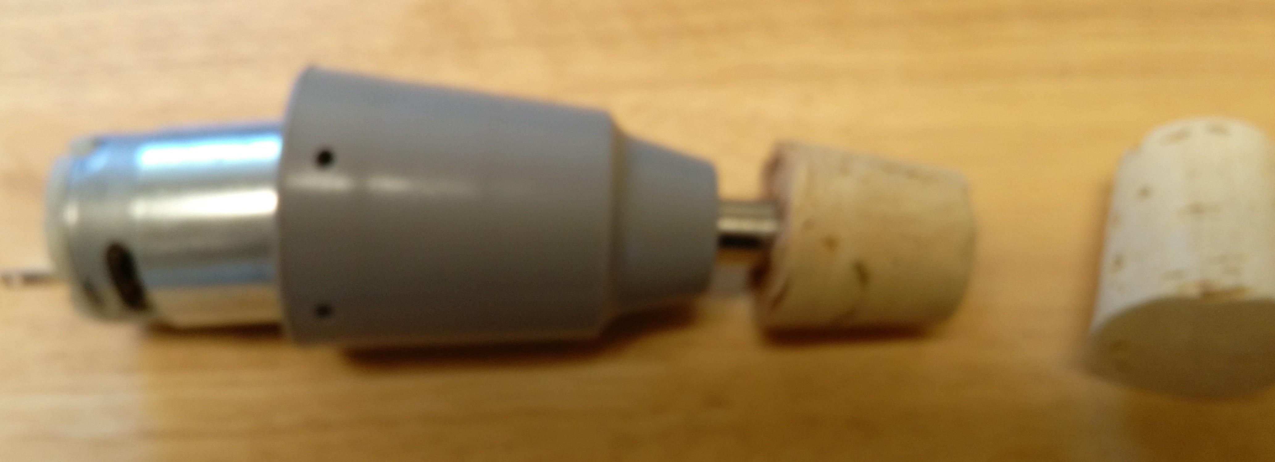
I was trying to use a bolt with a hex head and grommet but it wouldn't quite fit right, so I switched to a (real) cork.
The coupler is held loosely by the T connector, but holds the bottom of the motor.
The larger pipe supports the smaller. I'm not using lubrication since it seems to work when clean. The T rotates around with the smaller pipe and sits on the housing, I drill a hole in the pipe into the coupler for the wires to come out. The assembled version is pic 3.

I needed to use a 1-1/8" cork, cut the top off, and drill a hole. And added some glue:


 tz
tz
Discussions
Become a Hackaday.io Member
Create an account to leave a comment. Already have an account? Log In.