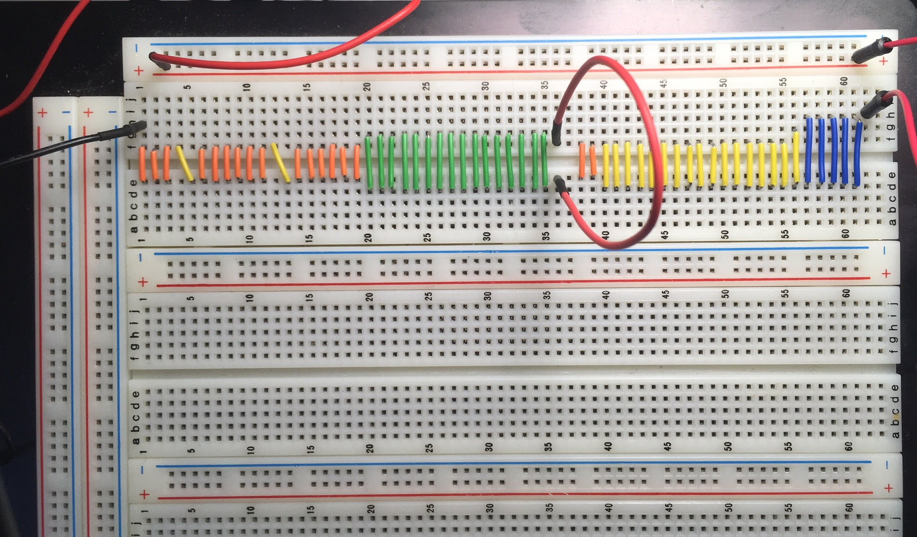
I don't have backplane yet, so I can use breadboard instead ( it is Bread Board friendly Q-bus after all ; )

Couple yellow diagonal wires on the left are for BDMGO-BDMGI and BIAKO-BIAKI deasy-chains.

Actually if CPU module is the last board then those two wires should be rotated, because CPU generates both BDMGO and BIAKO so they should go from right-top to bottom-left, but for now it doesn't matter because we don't use DMA or interrupts...
Now we will try to do something with LCD 16x2 that has 8-bit parallel interface. Simple circuits from 74LS32 OR-gates and couple 74LS374 registers does the trick - by writing to address 0xFF00 it will store 16-bit value on registers to be used to control LCD. Important thing when you are playing with LCD is delay between commands during LCD initialization and work that should be long enough for LCD to work properly. To implement precise delays we will use PDP-11 instruction sob (subtract 1 and branch if not equal to 0):
    mov #100,r0 ; 100 cycles of sob
delay1:
    sob r0,delay1
Step-by-step run of the 1st draft of the test program showed that 1 cycle takes 24 CLCI ticks (8 ticks to read sob instruction from memory, another 8 ticks to read NEXT instruction and then another 8 to execute branch), so we can easily compute for how long we should cycle to perform 15ms, 5ms and 1ms delays:
decimalnumbers
    org 0
    .word 0100H,0E0H ; reset vector
    org 0100H
start:
    mov #12500,r0 ; delay 15 ms for 20 MHz
delay0:
    sob r0,delay0
    mov #init,r4
initloop:
    movb (r4)+,r0
    beq endinit
    com r0 ; invert character
    bis #0FF00H,r0 ; set all bits of higher byte
    mov r0,@#0FF00H
    bic #800H,r0 ; inverted E=1
    mov r0,@#0FF00H
    bis #800H,r0 ; inverted E=0
    mov r0,@#0FF00H
    mov #4167,r0 ; delay 5 ms for 20 MHz
delay1:
    sob r0,delay1
    jmp initloop
endinit:
    mov #msg,r4
loop:
    movb (r4)+,r0
    beq endloop
    com r0 ; invert character
    bis #0FF00H,r0 ; set all bits of higher byte
    bic #200H,r0 ; inverted RS=1
    mov r0,@#0FF00H
    bic #800H,r0 ; inverted E=1
    mov r0,@#0FF00H
    bis #800H,r0 ; inverted E=0
    mov r0,@#0FF00H
    mov #833,r0 ; delay 1 ms for 20 MHz
delay2:
    sob r0,delay2
    jmp loop
endloop:
    mov #0FFFFH,r0
delay:
    sob r0,delay
    jmp start

msg:    .byte    "Hello, World!!!",0
init:    .byte    30H,30H,38H,8H,1H,6H,0CH,0
As I wrote before I have one strange VM2 that is capable of running on 20 MHz and it says "Hello, World!!!" now :)
But I see that 20 MHz is too much for VM2 anyway - it is glitching and eventually stops showing anything meaningful on LCD. Lower frequency 16 MHz is much more stable (no glitches)...
 SHAOS
SHAOS
Discussions
Become a Hackaday.io Member
Create an account to leave a comment. Already have an account? Log In.