127 TowerPro Servos, one I2C interface.
Taking the cheap and strong TowerPro MG995 servos (and siblings) and reprogramming them to accept commands and report position via I2C.
Taking the cheap and strong TowerPro MG995 servos (and siblings) and reprogramming them to accept commands and report position via I2C.
To make the experience fit your profile, pick a username and tell us what interests you.
We found and based on your interests.
A comment from [gficht] on the previous log asked "How do you plan on controlling the i2c lines with no pins to spare?". Which is a great question, and I thought it would be better to respond with a longer post. [Radimor] suggested 1-wire. I've considered both.
On the micro, there is one spare pin - pin 4, which is the original pulse signal input. My first thought was to use 1-wire on this pin, really easy, no circuit mods required - can even use the original cable. However, after looking at the datasheet for this I/O pin, it is only capable of being an input. There is no output driver. I also want an output so that you can also retrieve information on the servo position and torque and other such parameters. 1-wire also needs some rather accurate timing which might be tricky to bit bash on the PIC12 (while doing everything else at the same time).
For I2C you need two pins, one for the clock and one for the data. The data needs to be an output, the clock could be an input only (since it is driven by the master), but if the clock is an output then we could do clock stretching to adapt the clock rate.
The servo circuit has an 8MHz resonator connected between pins 2 and 3. The PIC12F675 has an internal 4MHz RC oscillator. So we can take the resonator off, and use those pins as I/O. Two spare I/O pins, and one spare input pin. The cost, is a halving in performance for the micro, down to 1 million operations per second (4 cycles per op).
The resonator is also a through-hole component, so soldering two wires will be relatively easy.
The remaining question is, what would you do with the spare input pin? Drop your ideas in a comment.
Got me a PICkit2 programmer clone and a SOIC8 test clip from the good people at banggood. If you intend to use linux as your programming environment - get the PICkit2, NOT the PCIkit3. There is no linux driver for PICkit3.
I'm currently setting pk2cmd up on my Ubuntu machine, following http://iam-saminda.blogspot.co.nz/2015/03/chipset-programming-with-linux-1-pickit.html and http://hackaday.com/2010/11/03/how-to-program-pics-using-linux/
$ sudo apt-get install build-essential libusb-devDownload the PICkit2 driver source. It doesn't seem to be hosted by microchip any more, but it is on sourceforge. https://sourceforge.net/projects/pic-linux/
untar the source and cd into the directory.
$ cd pk2cmdv1.20LinuxMacSource
$ make linux
$ sudo make install
Check that it installed (with the pickit2 plugged in):
$ pk2cmd -?V
Executable Version:    1.20.00
Device File Version:   1.55.00
OS Firmware Version:   2.32.00
Operation Succeeded
The PICkit2 was surprisingly simple to setup. The only hiccup I encountered is to tell pk2cmd where to find the PK2DeviceFile.dat file. Specify the directory containing it with -B/usr/share/pk2/ or put it in your PATH or current directory.
Now we need to plug the programmer onto the chip.
Find the pinout of the PICkit2 on page 9 of its datasheet.
http://ww1.microchip.com/downloads/en/DeviceDoc/51553E.pdf
I wrote the signal names on the back so that info is always where it needs to be.
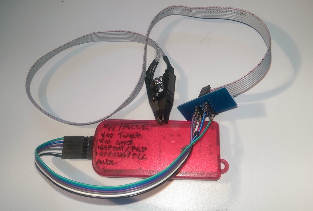
We've got to prepare the servo PCB a little for in circuit programming.
Trim the sides of the test clip so that it fits between the gaps of the other components (regulator, cap and resistor). Attach the test clip snugly.
(First time I did this, I just soldered wires to the appropriate pins).
Now for the moment of truth ... to ask it what the chip is on the other end (remember we don't know even if it is a PIC at all yet), ... drum roll please ..., No, then just blink the LEDs on the programmer then ...
$ pk2cmd -B/usr/share/pk2/ -P
Auto-Detect: No known part found.
Ah NO! Fail. What's wrong?
I reseat the soic8 test clip two dozen times. Trim it some more. Bend the pins inward so they make better contact. Still no luck. So I start desoldering bits:
Success!
$ pk2cmd -B/usr/share/pk2/ -P
Auto-Detect: Found part PIC12F675.
Our device is a PIC12F675! http://www.microchip.com/wwwproducts/Devices.aspx?product=PIC12F675
So we need to remove the capacitor attached to pin 7 of the PIC. It is affecting the slew rate on PGD/ICSPDAT signal from the PIC. This was its purpose of course - to be a low-pass anti-aliasing/noise reducing filter for the potentiometer input, but it does its job too well for in-circuit programming.
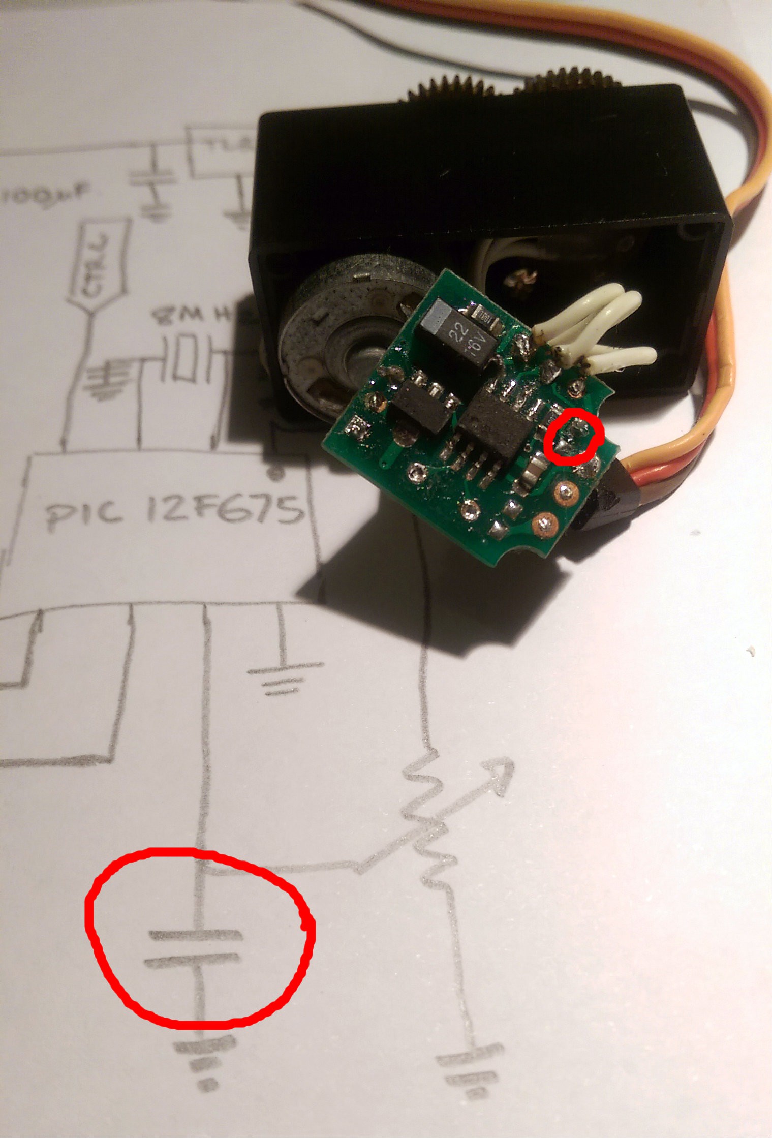
Sat down last night, with a pencil and paper, broke open a servo to work out what was inside.
We've got some metal gears, ball bearings, a brushed motor, a potentiometer and the interesting bit -- a circuit board.
The servos are labeled as "DIGI", which most people would take to mean digital. There are discussions on RC forums about these servos and if they are actually digital and how good they are. Apparently digital servos are better - better holding torque, less dead band and more responsive. The forum consensus was that they aren't digital (because digital servos should be expensive). I'm not into my RC vehicles so I don't know much about servos, but I am a trained electronics engineer. As we shall soon see these servos are in fact digital (and i'd suggest that analogue servos would be more expensive).
Inspecting the circuit board inside we find:
So with my pencil I traced the circuit, made a few educated guesses and reversed out a schematic diagram.
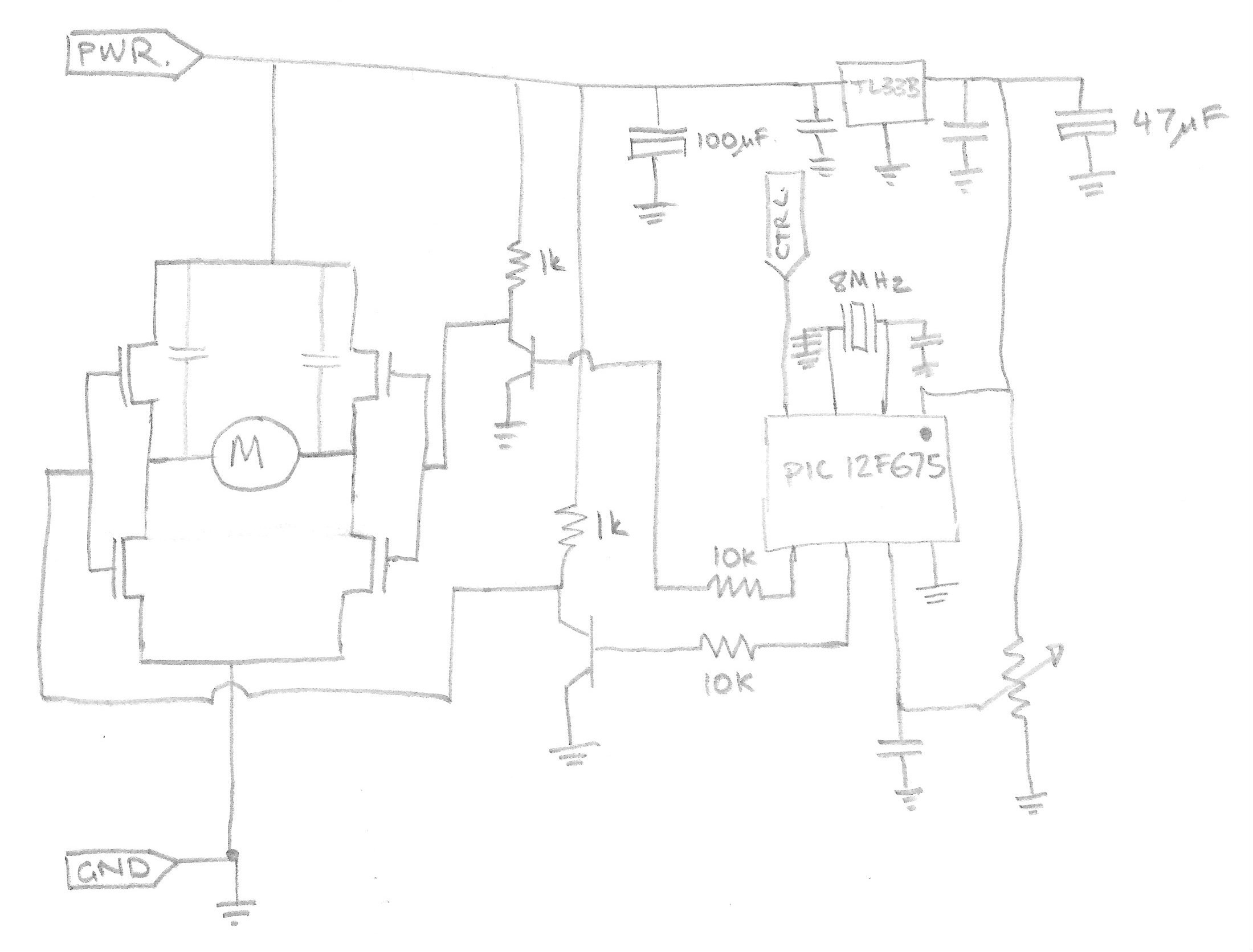
Pretty much what i'd expect. Nothing crazy. Actually its a well designed circuit.
The two SOIC-8 packages (next to the motor connections) contain MOSFETs connected in a full H-bridge configuration. Thus you can drive the motor in either direction. They appear to be something like an IRF7309, housing an N and P type MOSFET, making a half bridge each.
The transistors provide a voltage gain to drive the MOSFETs properly to full rail, instead of just the 3V available from the controller chip (remember we don't know what it is yet ;-) ). The transistor will invert the signal going through it. A high voltage at the controller will drive current into the transistor base, which will turn it on, pulling the output voltage to ground. When the transistor is off, the 1kohm resistor will pull the output voltage back up to the positive rail.
The final component of question is the 'contol' IC. In an attempt to protect the design the top of the IC has been scraped to remove the markings. I suspect/hope the IC is a microcontroller.
The micro's pins are connected to:
Pin 1. VCC
Pin 2. Oscillator
Pin 3. Oscillator
Pin 4. H-bridge control
Pin 5. Servo's PWM control input wire
Pin 6. H-bridge control
Pin 7. Potentiometer input (ADC?)
Pin 8. GND
Educated guess says the controller chip is probably a PIC, since they are cheap and well known. After a bit of internet searching I can match the pin-out to the 8-pin microcontrollers of the 12-series PICs. The PIC12F510 being the most likely.
I started this project in August 2008, that is almost exactly 7 years ago. Problem was I had another project on the go at the same time, and a PhD to finish. Then came the paying job and some new interests. Needless to say, this one got left in a box, half finished.
Luckily I left myself some notes, so hopefully I can skip some of the stumbling blocks I hit before. As I work back to the undiscovered edge of this project I'll post what I have found. I'll begin with the reverse engineering of the servo and work towards reprogramming it. Spoiler alert, I already know that it can be done, and I've already given some of that away in the project title and description. But lets pretend that we don't know because a voyage of discovery is more exciting reading (and writing).
Create an account to leave a comment. Already have an account? Log In.
No idea, not that far in yet. But yes that might be a concern.
Next log post will include a reverse engineered schematic. There is a 3v3 regulator to power the micro with some good sized caps around it so hopefully not to much noise from the motors coupling back in.
Become a member to follow this project and never miss any updates
 Solderking
 jurc192
 Shranav Palakurthi
 Nick Sayer
Any issues with noise on the I2C lines? Great idea!