Sat down last night, with a pencil and paper, broke open a servo to work out what was inside.
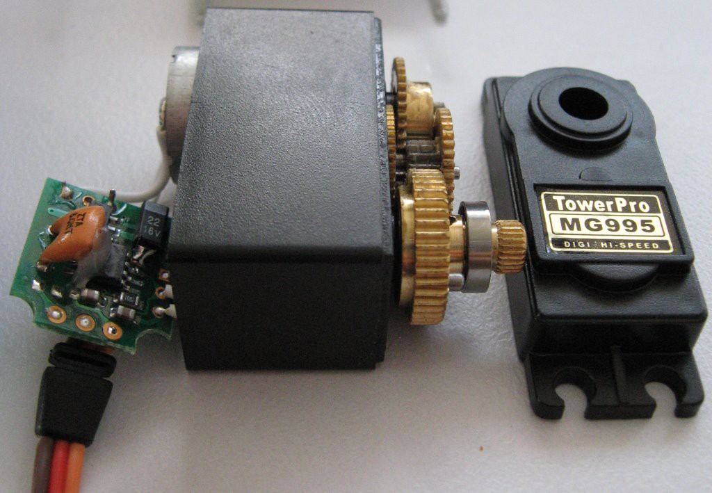
We've got some metal gears, ball bearings, a brushed motor, a potentiometer and the interesting bit -- a circuit board.
The servos are labeled as "DIGI", which most people would take to mean digital. There are discussions on RC forums about these servos and if they are actually digital and how good they are. Apparently digital servos are better - better holding torque, less dead band and more responsive. The forum consensus was that they aren't digital (because digital servos should be expensive). I'm not into my RC vehicles so I don't know much about servos, but I am a trained electronics engineer. As we shall soon see these servos are in fact digital (and i'd suggest that analogue servos would be more expensive).
Inspecting the circuit board inside we find:
- three SOIC-8 ICs which have had their marks scrubbed off (thanks Mr Manufacturer guy),
- a couple of electrolytic capacitors,
- some surface mount capacitors and resistors,
- an 8MHz ceramic resonator,
- two 3 pin transistors,
- a 3.3V linear voltage regulator.
So with my pencil I traced the circuit, made a few educated guesses and reversed out a schematic diagram.
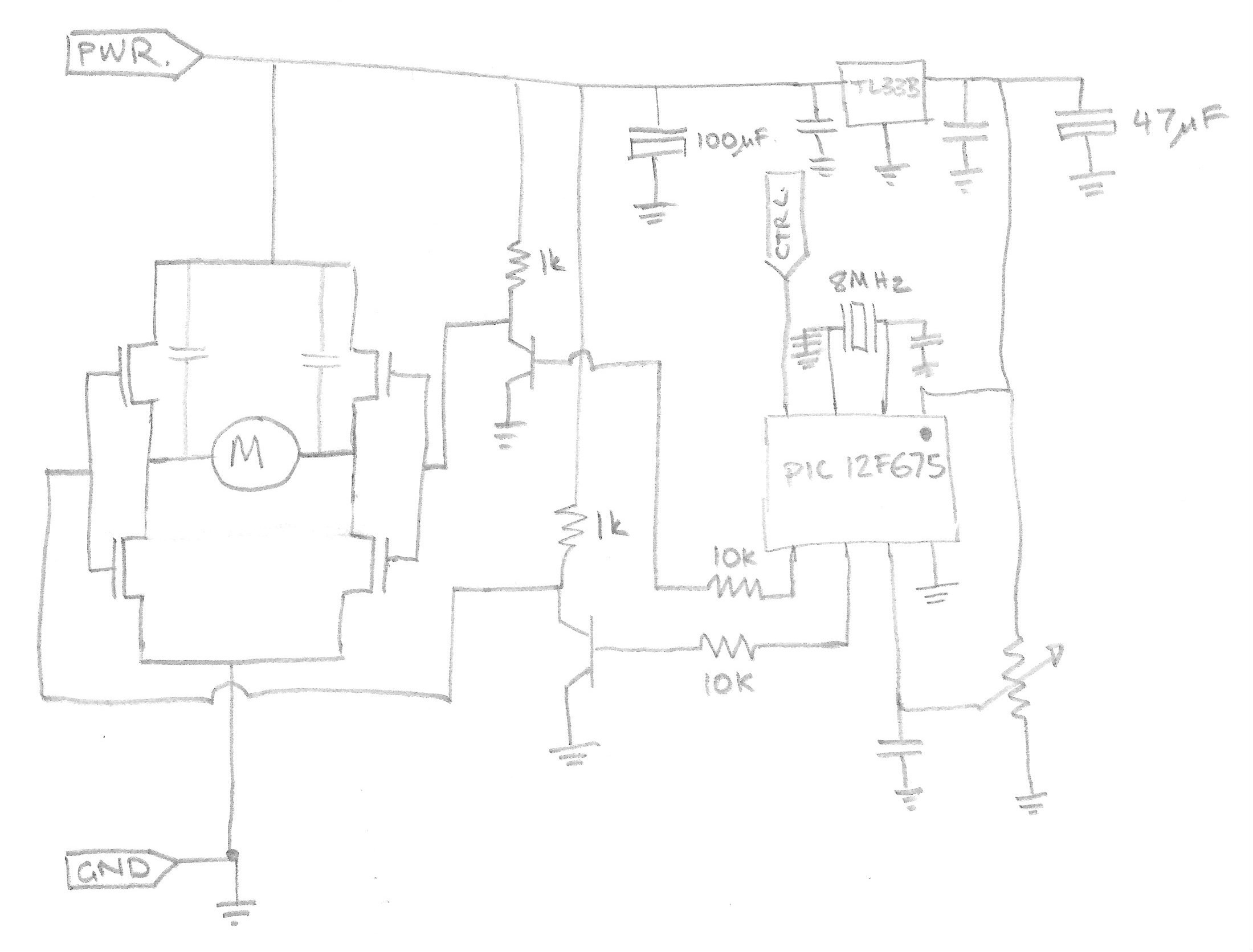
Pretty much what i'd expect. Nothing crazy. Actually its a well designed circuit.
The two SOIC-8 packages (next to the motor connections) contain MOSFETs connected in a full H-bridge configuration. Thus you can drive the motor in either direction. They appear to be something like an IRF7309, housing an N and P type MOSFET, making a half bridge each.
The transistors provide a voltage gain to drive the MOSFETs properly to full rail, instead of just the 3V available from the controller chip (remember we don't know what it is yet ;-) ). The transistor will invert the signal going through it. A high voltage at the controller will drive current into the transistor base, which will turn it on, pulling the output voltage to ground. When the transistor is off, the 1kohm resistor will pull the output voltage back up to the positive rail.
The final component of question is the 'contol' IC. In an attempt to protect the design the top of the IC has been scraped to remove the markings. I suspect/hope the IC is a microcontroller.
The micro's pins are connected to:
Pin 1. VCC
Pin 2. Oscillator
Pin 3. Oscillator
Pin 4. H-bridge control
Pin 5. Servo's PWM control input wire
Pin 6. H-bridge control
Pin 7. Potentiometer input (ADC?)
Pin 8. GND
Educated guess says the controller chip is probably a PIC, since they are cheap and well known. After a bit of internet searching I can match the pin-out to the 8-pin microcontrollers of the 12-series PICs. The PIC12F510 being the most likely.
Discussions
Become a Hackaday.io Member
Create an account to leave a comment. Already have an account? Log In.
Just to confirm and add to the knowledge base, I also opened clones of the MG995 and MG996 and both used the AA51880 servo controller in 16 pin form. My PDI-6225MG servos have an unmarked (scraped) 20 pin chip. I'm guessing that with so many more pins than a pic would need this is probably also a servo controller?
Are you sure? yes | no
OK, I know this is an old thread, but I have an MG995 cracked open right now, I was excited that your schematic showed a voltage regulator.... There is no longer a voltage regulator, nor are there voltage translation transistors. All be warned not to rely on them being there.
Are you sure? yes | no
Indeed, I second zakqwy's "good sleuthing" :)
Are you sure? yes | no
Good sleuthing on the PIC. I'd be interested to see what you discover when you try programming it; I pulled apart a fancy digital servo (read: high-priced) and found it contained an FR6461 "digital servo controller". Something fully programmable could be a lot more interesting.
Are you sure? yes | no