Charles Ahrens
-
Shift Register Woes
07/15/2015 at 07:34 • 0 commentsI had originally designed the circuit with 7HC595N Shift Registers (my favorite "default" shift register) without considering the large current required for the Numitron tubes. I had intended to either multiplex them or have all 6 tubes displaying at once, but even a single tube displaying a single number would be ~100 mA, which was waaaaaay more than the poor little 7HC595N shift registers could put out. Not to mention that the ATMEGA chip can only sink about 200 mA max on each ground line. I wouldn't have noticed this problem at all and probably fried at least one of my shift registers had I not noticed that each number displayed on the Numitron in a test circuit was a slightly different brightness. A number such as 1 would be super bright, since it was only 2 segments lit, whereas 8 would be super dim, since all segments were lit. In frustration, I began my search anew, after having already purchased 10 of the 74HC595s to use in the circuit.
Someone online at one of the Arduino forums had figured out that a TPIC6B595N shift register with high current capabilities could easily sink enough current to handle a Numitron tube. The only problem was that any shipper in the US charged about $5 per chip with quick shipping, and any shipper in China had slow shipping, but ~$0.50 per chip. I went with the Chinese seller, and was pleasantly surprised with the quick shipping. Now I just need to redesign the circuit so that I can use the 74HC595s for the Nixies and the TPIC6B595Ns for the Numitrons. -
Circuit Design
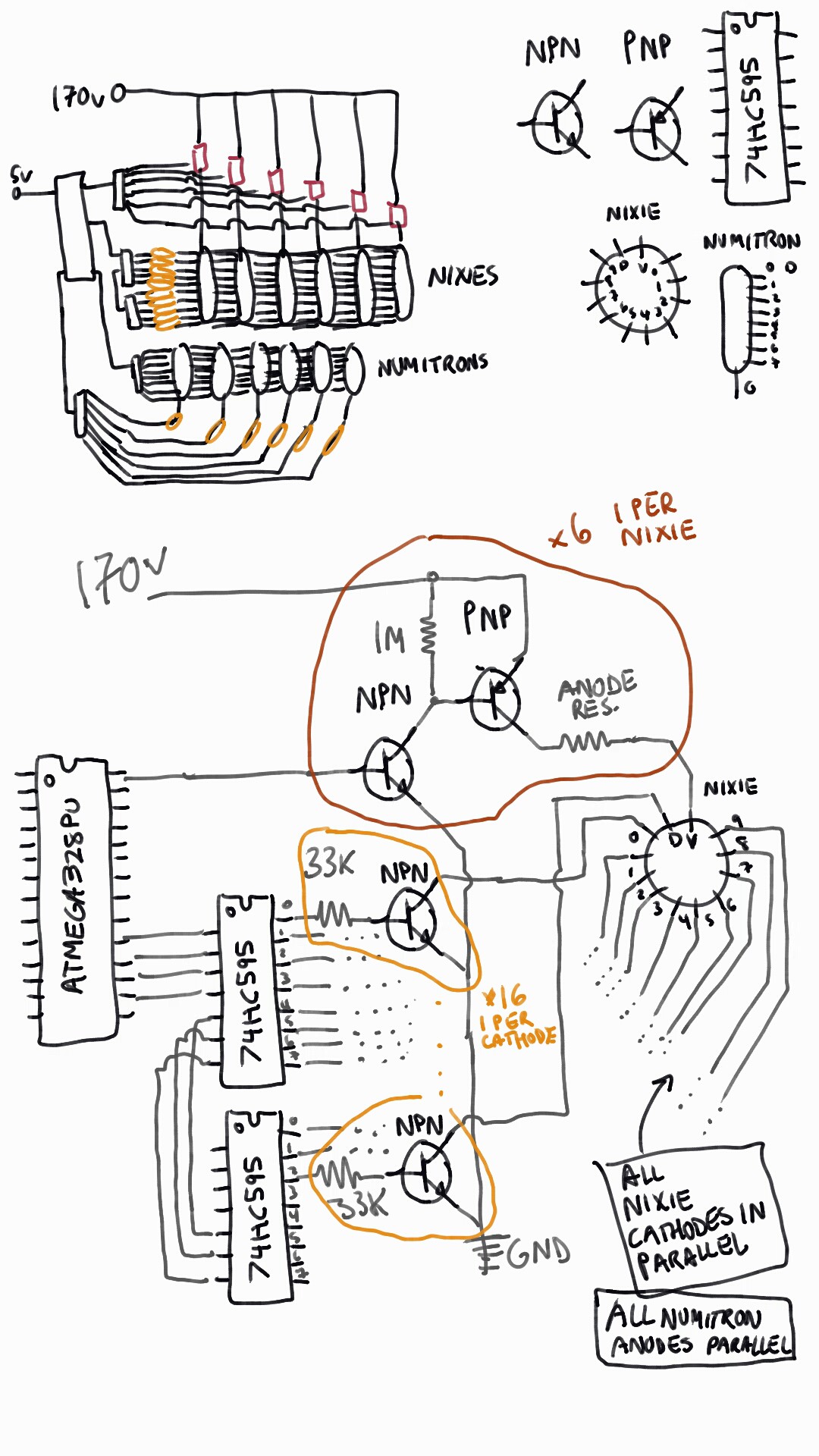
07/15/2015 at 07:27 • 0 commentsI designed the circuit to light the tubes as shown below, with daisy chained Shift Registers (74HC595) connected to the High Power NPN Transistors (MPSA42) to each cathode of the Nixie tubes so that the high voltage could drain through the tube, through the transistor, and to ground without frying the ATMEGA chip I am using to control it. I will connect all the cathodes of each Nixie in parallel (tube 1's 5 connects to tube 2's 5 to tube 3's 5, etc.), but the anodes to separate control circuits in order to multiplex the tubes. For the numitrons, I intended a very similar circuit, where all the anodes of each tube are connected in parallel, and the common cathode is connected to ground when I want to display on that tube. I also considered running each Numitron on its own shift register and daisy chaining them together, but I want to wait and see how the circuit works first.
![]()
-
Tube Layout
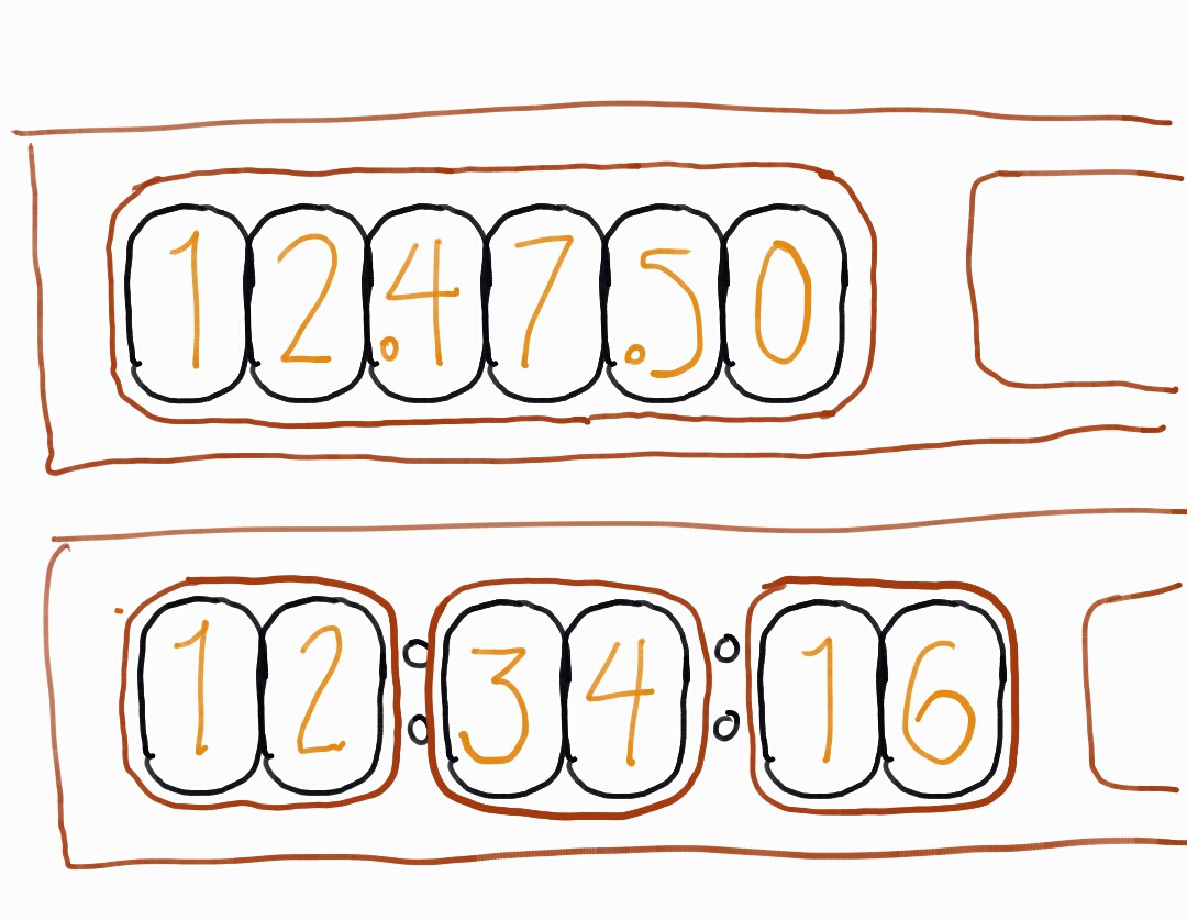
07/15/2015 at 07:18 • 0 commentsI decided to go with the 3 groups of 2 tubes for the front of the clock, since it will be easier to separate the hours, minutes, and seconds this way. I might change back to all 6 in a line in order to make the case easier to produce, though. I'm using IN-12B nixie tubes, so there is a little dot on each tube that I can access to make the hours, minutes, and seconds easier to tell apart.
![]()
Nixie and Numitron Clock
Combining the retro awesomeness of Nixie tubes and Numitrons to make one cool clock.