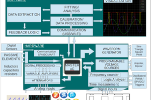
The project can be divided into five subsystems as shown below. The functions of each of these subsystems is described below:-

1. Analog Front End: It is made of various sensor modules which convert
physical quantities into electrical signals. Each sensor module is integrated
into respective measurement probe and the kind of physical quantity being
measured depends on the kind of probe connected to the scope. The
electrical signals from the sensor output is then attenuated and level shifted
so that it matches the input range of ADC. The attenuation factor depends on
the output range of the sensor connected to the scope. It is controlled by the
microcontroller with the help of analog multiplexers.
2. Data Acquisition System: This subsystem is made of two High speed
ADC’s, two MAX4203 buffers, two Dual DAC’s and two Atmega32
microcontrollers. The ADC is used to sample electrical signals. After sampling
the values are stored in either atmega32 or in ADC internal capture buffer as
required. The two Dual DAC’s along with the MAX4203 set the top and
bottom reference for the two ADC’s.
3. Main Microcontroller: The main microcontroller plays a central role in the
operation of integrated scope. It coordinates the operation of all other
devices. It takes input from Data Acquisition System, Control Panel and USB.
All these three inputs are used for rendering the image. As an example if the
user turns on the grid lines, the microcontroller will carry out a routine which
writes the grid lines on screen.
4. Control Panel: The Control Panel uses three Atmega8 microcontrollers to
record the status of all switches, Rotary encoders and buttons used in the
control panel. Its primary function is to record the inputs given in control panel
and send the data to main microcontroller whenever required.
5. LCD Screen: This scope uses a 480*272 4.3 Inch TFT LCD Module for
displaying the waveform and other relevant details as required. It is also
integrated with a touch screen interface which facilitate touch screen
operation.

 Jithin

 ensafatef
 Markus Leutwyler