 DeepSOIC
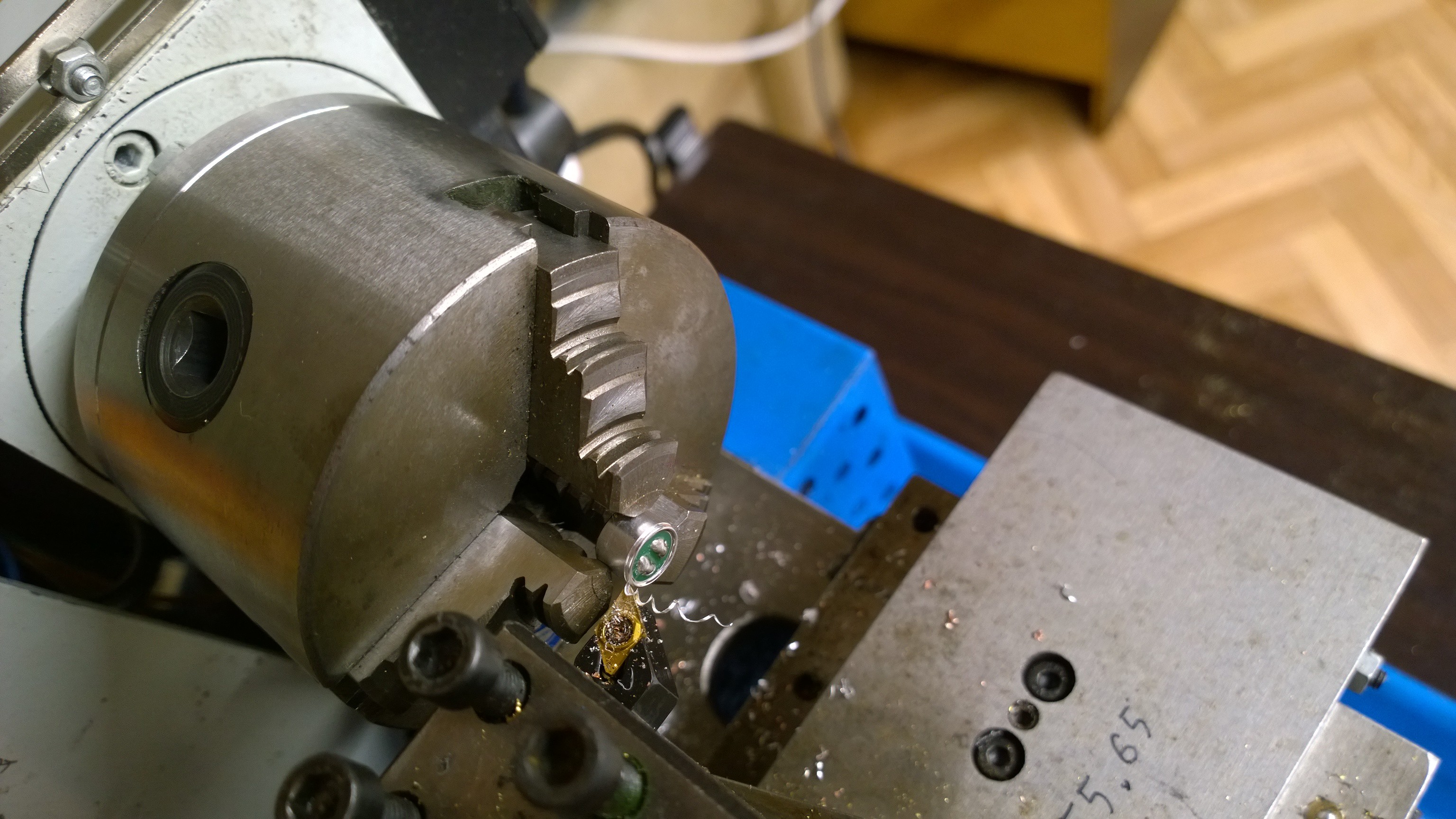
Let's take one apart, to see how it works, and how can we make it deafer.
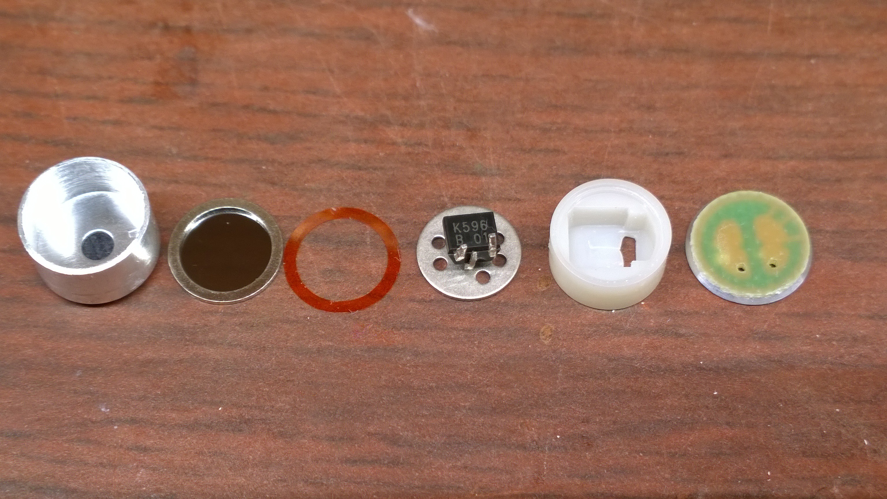
Left to right: outer shell, diaphragm stretched on metal ring, a spacer ring that sets capacitor plate separation, fixed plate of capacitor with jfet (datasheet) spot-welded to it, another spacer, and back PCB.
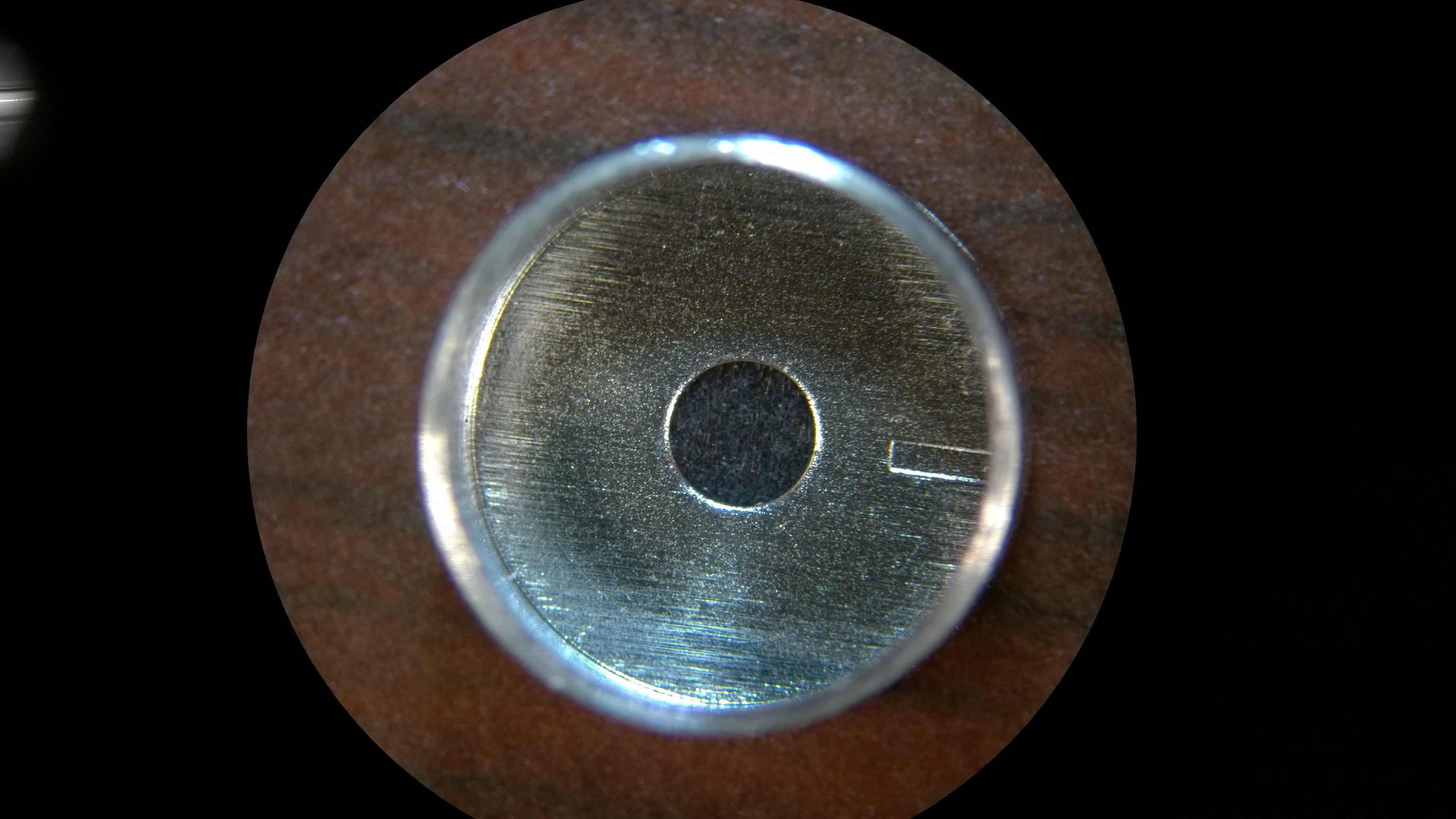
There is a small indent on the outer shell, which likely is the leakage path for air, to slowly equalize pressures inside and outside of the microphone.
Here, I doodled a cross-section view, and a schematic.
 As the sound wave passes by, it changes the air pressure outside of the microphone. The difference in pressures between outside and inside causes the diaphragm to bow, until the pressures are equalized (assuming the diaphragm is very flexible). The capacitor's capacitance changes, and because of the built-in electric field thanks to electret, some voltage appears on the capacitor. That change is amplified by the jfet.
Note that other microphones may have somewhat different geometry of elements, but the basic principle should be the same.
Discussions
Become a Hackaday.io Member
Create an account to leave a comment. Already have an account? Log In.