I'm going to have to adjust my schedule. :)
I was going through my project wiring to start making a wiring diagram. The way that I wired my prototype is with a bunch of jumper wires. I have been planning on this being a DIY kit that the user assembles. So I was going to include a bunch a jumper wires and diagram and the use would go to town wiring it up.
But the more I thought about it, the less I like that solution. It isn't elegant and requires some wire striping and soldering. In the back of my mind I had been kicking around the idea of making a PCB, but didn't have it in my schedule and thought that jumper wiring would be fine.
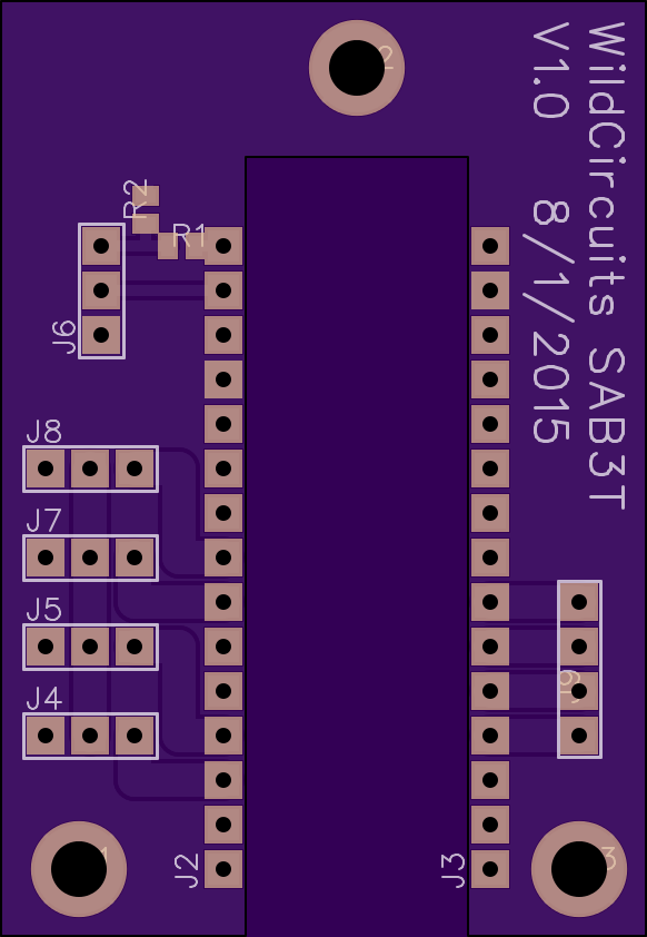
So the PCB for SAB3T is a 2 stage approach. Stage 1 is basically breakout boardfor an Arduino nano. Here it is:

This board has 3 pin headers for the servos to plug into, a 4 pin header for the touch screen connection, and a 3.3v compatible serial header. That is all the stuff that was wired with jumpers. I put the board order in with OSHpark last night, but it is highly likely that I won't be getting the boards in before my ship date. I have access to a PCB router at work, so I'll be running off a few boards at lunch break this week. If my OSHpark boards don't arrive in time I'll build my 3 demo units with the boards from the PCB router.
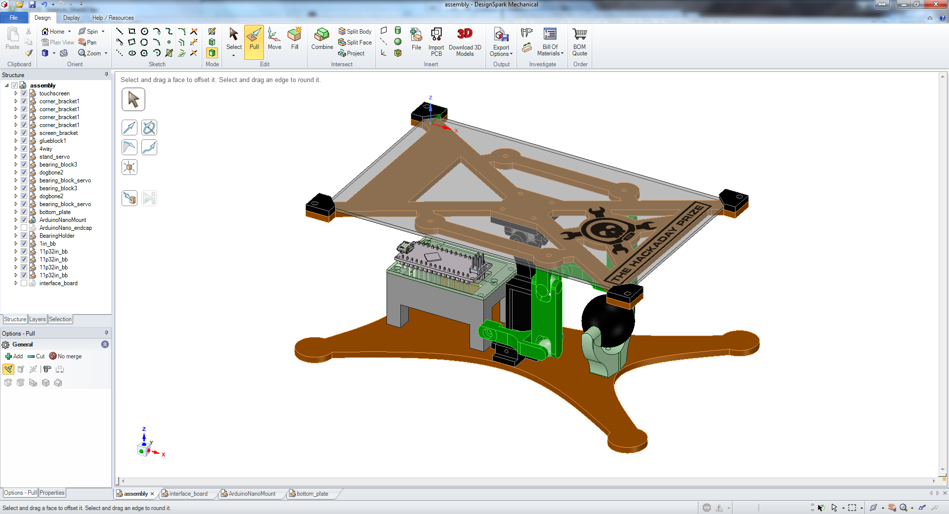
This make the wiring significantly easier and more robust. Here is what it will look all assembled:

Stage 2 will be a custom Arduino with the proper connections broken out and a couple of mounting holes. I won't be looking into that until after the Best Product competition is done.
 Tim
Tim
Discussions
Become a Hackaday.io Member
Create an account to leave a comment. Already have an account? Log In.