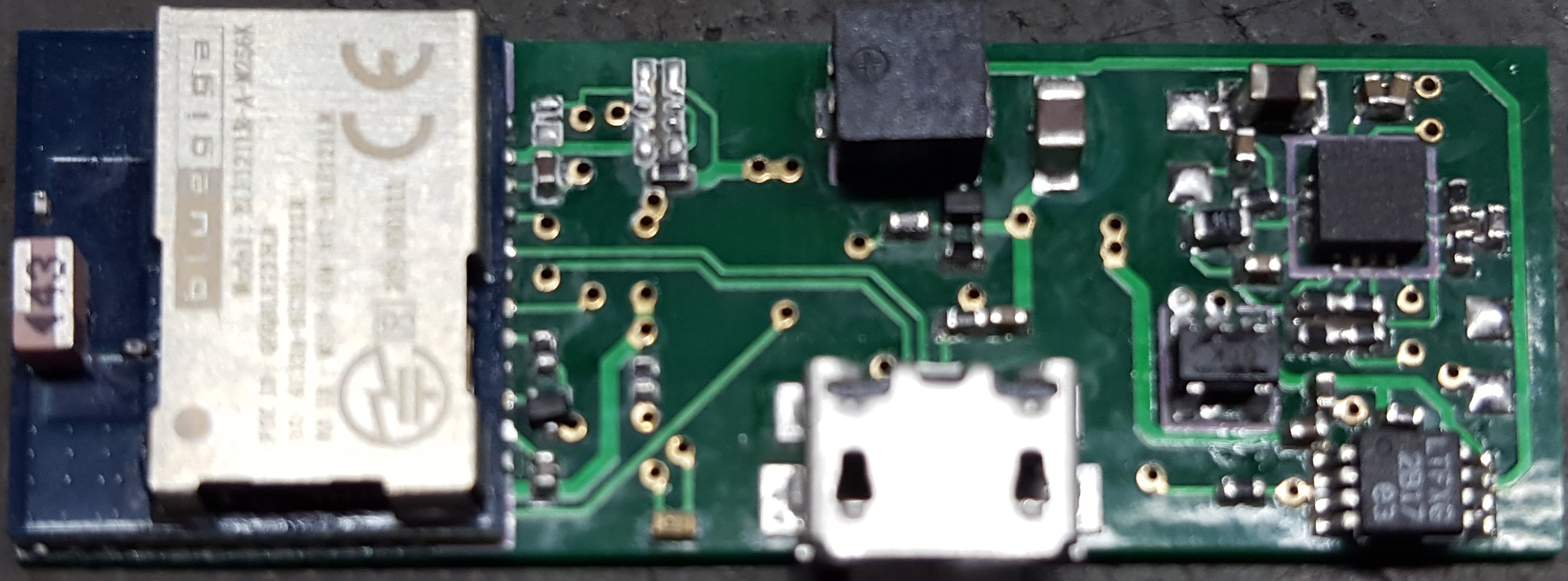
The revision 7 prototype has a problem cold starting on solar power. Its worse than just that it doesn't cold start, when the system receives solar power in a dead battery state it will cause a further drain of the battery.
The problem stems from the lack of isolation of the system load from the battery when the battery protection IC has it disconnected. This problem is a bit tricky to fix. Isolation can be done on the high side with a PFET driven by VBatOk. This is the solution recommended by the datasheet.
VBatOk is an active high so the PFET must be driven by an inverted. The two key problems are we need an inverter that will draw next to no quiescent current and work referenced against VStor. VStor is set by a combination of factors. Its limited by both the battery voltage and the battery over-voltage set point. The lowest expected voltage is the battery cutout voltage of 3.2. However its also possible in long periods of disuse for the battery to drop lower. At lower voltages the inverter may be left with its output floating putting the isolation PFET in an undefined state. Testing of a prototype will determine if this solution will work.
I am having 2 additional prototypes made for testing purposes. They will be used additionally to test the buzzer leakage current if there is any, for a performance comparison against the BLE112 radio module and finally to test the BQ25505 as an alternate energy harvesting chip.
Switching to the BQ25505 may allow removal of the LTC4071 lowering BOM costs. The BQ25505 has a active low primary battery enable output so we would also not need the inverter. Its shipping mode with a 5nA quiescent current allows for it to replace the LTC4071 with sufficient performance.
 The r7 prototype PCB's where obtained from PCBCart. Only 85$ for 50 boards and I got them all within a week and a half. The holes in the vias where a bit off center but they never broke the edge. The board quality was quite good. However the 0.4mm PCB's are not a flexible as I had hoped they would be. They don't bend much at all.
 PCB cart even threw in a nice stainless steel solder paste stencil. I used this to make the prototype board. The solder paste on the bottom of the BLE121LR ran together a bit but in spite of that every joint came out perfect on the first go. I was able to assemble, solder, and program the board in only 30 minutes. Much faster than my previous prototypes done with hand soldering.
 DrYerzinia
Discussions
Become a Hackaday.io Member
Create an account to leave a comment. Already have an account? Log In.