DrYerzinia
-
More Light Tests
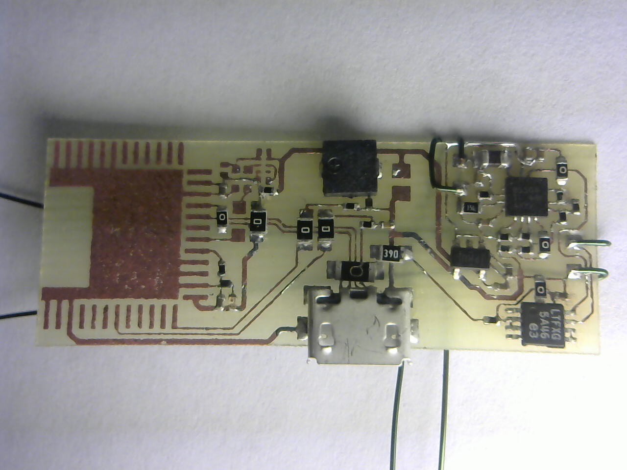
08/11/2015 at 08:29 • 0 commentsThe power supply section of the revision 5 board of the Sol BLE Tracker is built. And of course its time to test how much charge current I get. In these tests its drawing all the quiescent current it would normally minus the 1.6 uA of the BLE radio.
![]()
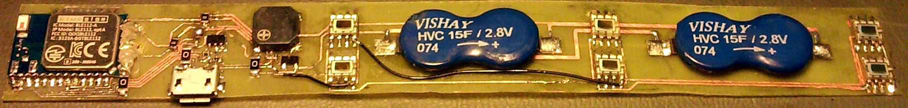
Revision 5 minus the radio.
![]()
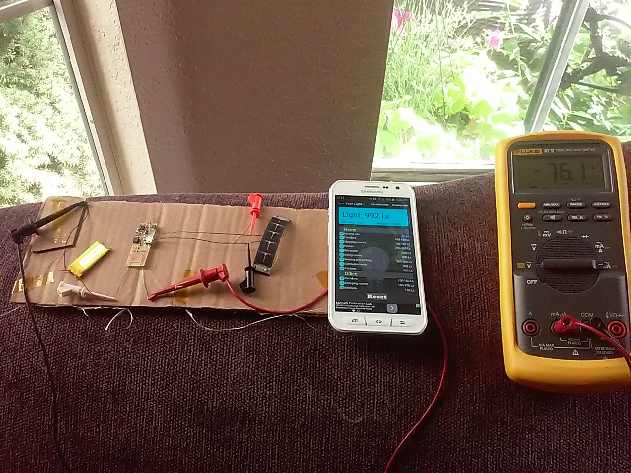
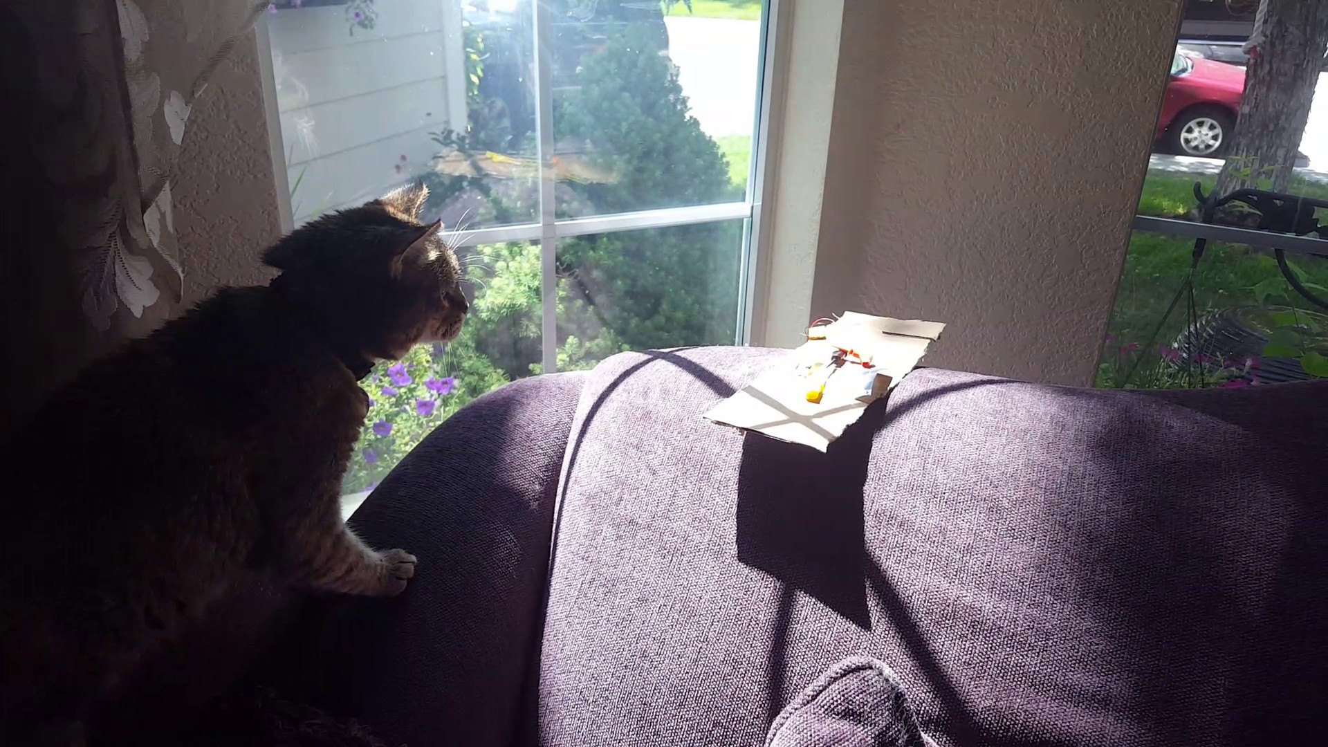
Above you can see the by the window couch test. 992 lux on a sunny day providing 76uA of charge current. 7x more than enough to run the system.
![]()
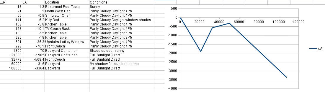
The readings from the real world tests are not a nice strait line and I suspect this is because of how much the angle of incidence affects the lux meter on my Galaxy S6 Active but we can still draw some useful conclusions from it. The main thing to take away is that on a sunny day in the open areas of the house the ambient light is going to be enough to charge the system. Also if the cats spend just a few minutes a day in direct sunlight it will have no problem running forever without having to attach an external charger.
![]()
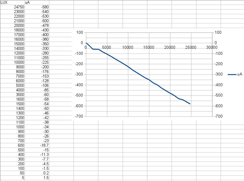
In the data for the microscope light test you can see a small jump where it also changes slope. That was where I moved the light physically closer rather than varying the input voltage to get a higher lux reading. The first set of sets showed a slope of 25 lux/uA. The second set 42/uA. The main takeaway here is we should expect to need 300+ lux to run the system. With a proper lux meter the real world measurements would likely match this figure as the angle of incidence problem would be solved. I expect this test to be fairly accurate as all the light is coming from one direction however the LED spectrum is not the same as sunlight.
-
Solar Power Measurments
08/07/2015 at 00:07 • 0 commentsSo I did the measurements on the power and I'll just get strait to the point here:
In direct sunlight it was charging at ~2mA. That works out to needed 7.2 minutes a day of direct sun to keep the device operating or for a full charge of the battery 5 hours of direct sun. So if your cat likes to sun itself for atleast 7.2 minutes a day or 5 hours a month you will never have to charge the collar. I measured about 80,000 LUX in this environment.
Alternatively on a sunny day the ambient light generates ~30uA of charge current. That's 3x the devices power requirement. So if the collar only gets ambient light 8 hours a day it should still be able to never need charging. I measured my ambient lighting at ~300 lux.
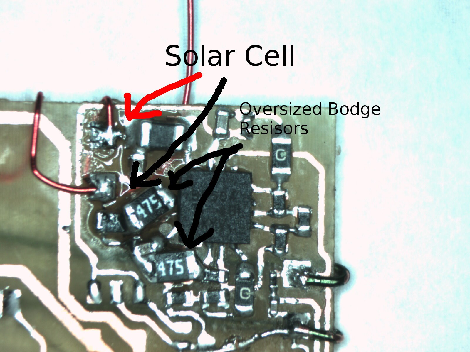
Those are the practical figures. Now I will go on telling the story of the adventure I had building and testing the circuit. First problem was fitting the bodge resistors on the board.
![]()
There not technically bodge resistors, just oversized ones because I forgot
to order the 0402's which will now be here on Saturday. I managed to barley get them in.
The next set back wasn't detected till I started probing the circuit. After applying sun to the cell I didn't get any boost conversion going. The chip wasn't loading down the cell and I got less voltage out than in!
So a quick look at the recommended application circuit schematic and I realized *DOE* I forgot a connection from VSolar to the VIn off the chip!
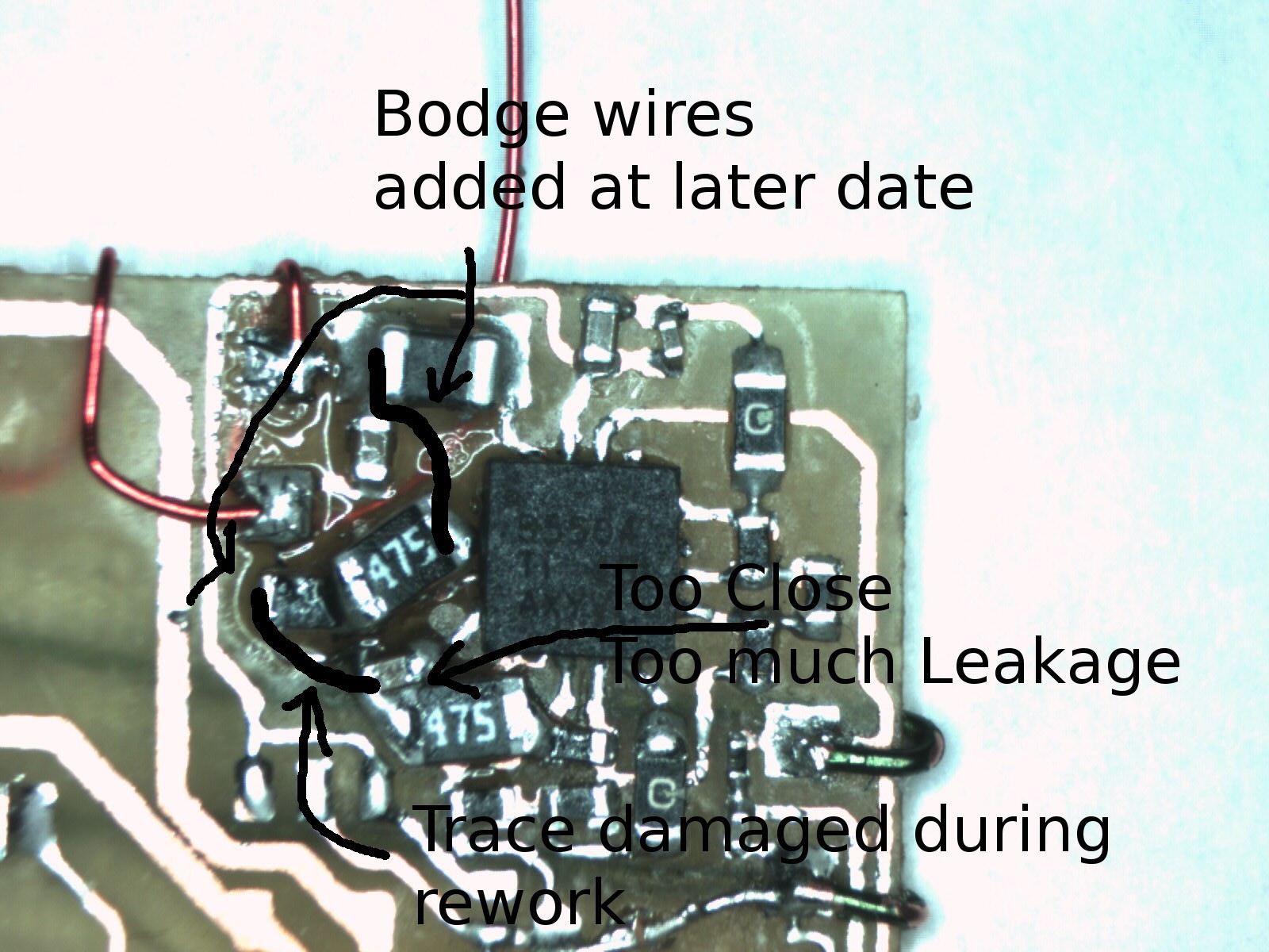
Time to add a bodge wire.
![]()
So I bodged in a wire from the resistor on the VIN to the inductor on the VSolar. And IT WORKED!
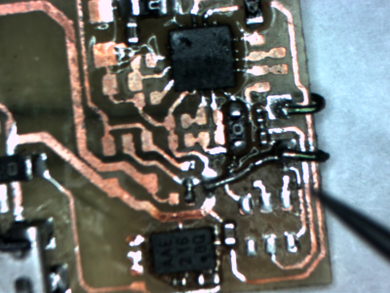
Only one strange problem, the voltage of the solar cell was oscillating up and down. Another trip to the datasheet and I understood why. The MPPT algorithm works on a 16 second cycle. It samples the unloaded solar cell voltage through a resistive divider which in this case give 73% of open circuit voltage and stores that in a capacitor for reference. Then feedback from that voltage its used to determine how much current to pull from the solar cell to boost its output to charge the battery. My first thought after looking at the circuit was just how very close that capacitor was to shorting back across itself to ground. And I did a bit of rework to move its important end to be more isolated. Broke a trace doing it and added another bodge wire.
You can see roughly the operation of that section of the circuit in the above image. After the rework, a thorough cleaning with isopropyl alcohol and some time for the alcohol to evaporate I had a much smaller oscillation. Only about 200 mV peak to peak or 7% full scale. I expect this figure to improve on a professional board where the whole thing will be reflowed with solder paste. Much less residue to reduce resistance between the sides of the capacitor. I am using the recommended X7R capacitor type for minimal leakage so it can't be that.![]()
Now that everything was working its time to test the circuit performance under real world lighting conditions the results of which are at the top of this post.
The location of the first setup. Full direct sun with occasional leaf![]()
interference. Yes the tree got in the way for a bit. And with 80kLux
we get a charge of atleast 2 mA. Way more than enough to charge and run
the collar.
![]()
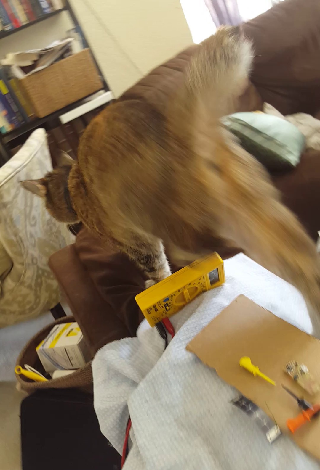
The next setup was on the back of the couch in the main TV room. The moment I started recording Fiona hopped up to check out what was going on and unexpectedly landed on the circuitry. Here I recorded 300 lux with my phone and a respectable 30uA current. Enough to run the circuit and charge at 2x the operating current.
I took away a few things from this experiment, first solar powered harvesting devices for radio networks have to be ridiculously efficient if they don't get direct sunlight. Ambient light at 300 lux is nothing compared to the raw 80000 lux power of direct sunlight. That's 260x more energy in direct sun! But thankfully with my designs 10uA current draw we can still pull it off with low light levels if we have to and as a last resort you can always charge the battery with micro USB. -
Sol BLE Tracker Prototype 4 Update
08/06/2015 at 02:17 • 0 commentsA quick update on the status of the Sol BLE Tracker. I'm just repeating whats in the video above in text down here so if you watched it there is nothing new below.
I'm currently working on producing the 4th prototype of the tracker, due to the smaller packages I used to save space I've been having some trouble with the soldering. I got everything on alright but while trying to rework a resistor when it somehow shorted to another trace underneath where I couldn't see I tore off a trace that went under a DFN transistor 1mm x 0.6mm and that made the battery protection section basicly a lost cause. I'm planning on changing that section to a LTC4071. Its a combined LiPo battery protection circuit as well as charger. It has lower quiescent current and requires less external components. No transistors in particular. Its also an MSOP-8 which will be much easier to solder than the 2 DFN transistors and the DFN charger package as well as taking up less overall space. The only downside is its only rated for 60mA current which the buzzer should draw more than. I think I can get around this with some decoupling capacitors near the buzzer. In the current design however both the charger and battery protection where tested to be working.
![]()
I continued to assemble the board despite this SNAFU when I discovered I did not order the 4.42M ohm 0402 resistors. These are part of the solar charge circuit. I'm going to try and get some 4.7M ohm 0805 resistors in there place to test with. I want to measure the current to or from the battery in various lighting conditions to make sure the charger is working as expected.
![]()
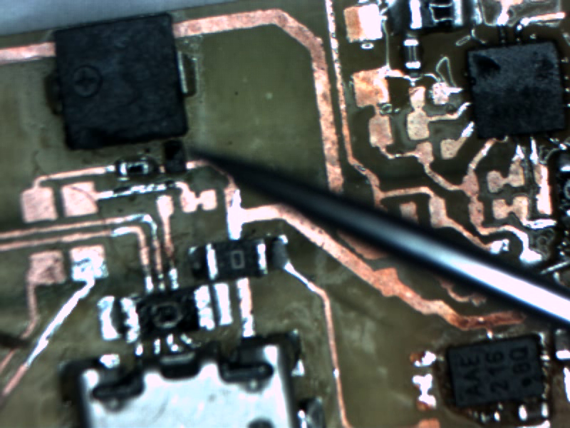
You can see in the picture below one of the NPN DFN transistors I used for the buzzer. I'm going to swap these out with SOT-923F package transistors which have leads. This way if something goes wrong I don't have to scrap the section they are in because of it and it will be much easier to solder them. They are bout the same size as the DFNs anyway. I changed to a smaller buzzer in this design it takes up about a quarter of the space the old one did. Another thing to note is all the jumper resistors. They are only in this design for ease of construction. The production PCBs will be made by FlexPCB. I'm going to use a second layer for the jumpers and use the bottom layer as a ground plane as well which should also help RF performance.
![]()
Expect an update about the current measurements to the battery from the solar charger in the next few days.
-
Current Status
07/24/2015 at 23:56 • 0 commentsI've already done a lot of work prior to creating this project on hackaday so this is just an overview of the past.
So far there have been 3 prototypes. The first was eaten by my dog. It was tested by Fiona for several days. It was discovered that the "SuperCaps" I had selected where more like batteries. They couldn't discharge fast enough to drive the Buzzer and couldn't charge fast enough to be reasonable. This led to my exploration of other options.
![Origional prototype with "Super Caps" made on very thin board.]()
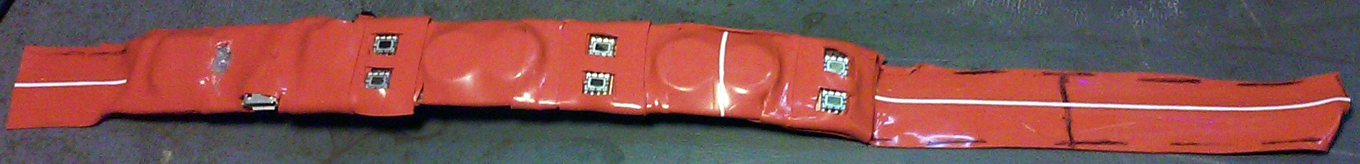
![Wrapped safely in silicone tape. Those cells where way to small to be useful.]()
![Apparently the doggy doesn't have enough chew toys so he has to resort to stealing my prototypes off of tables.]()
The second prototype was designed with a footprint for a rechargeable lithium coin cell. This also proved not to be able to supply the necessary current for the buzzer. Even with a large 100uF+ capacitor to buffer it couldn't keep up.
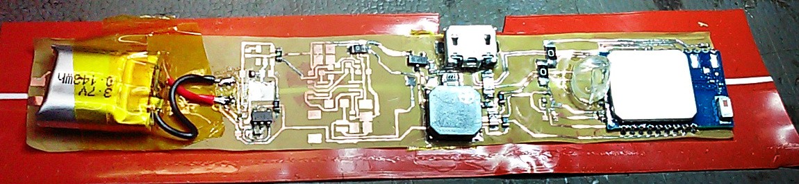
![Swapped out that lame coin cell for a 40mAH LiPo!]()
The third prototype just had an 1206 footprint on the edge to connect a second power board so I could experiment with alternate battery source. I had wanted something super thin and the thinnest LiPo I could find was still about 5mm thick. That is what I used for the 3rd and was the only power storage option that worked.
![Replaceable Power Board on the end! Ultimatly that was totaly poinless LiPo is the only way to go it seems.]()
I wired up the second prototype with the same battery as I was using for the 3rd and put them on Jasper and Fiona for testing. For insulation I sandwiched the boards between 2 layers of Silicon tape. They lasted for about 3 days before problems started occurring. The copper clad film was tearing around the Micro USB connector and cutting off the ground from the power. I expect the professionally produced Flexible PCB's will not have this problem. The batteries had hardly lost any juice over the 3 days and I estimated they would have lasted at least 4 months between charges.
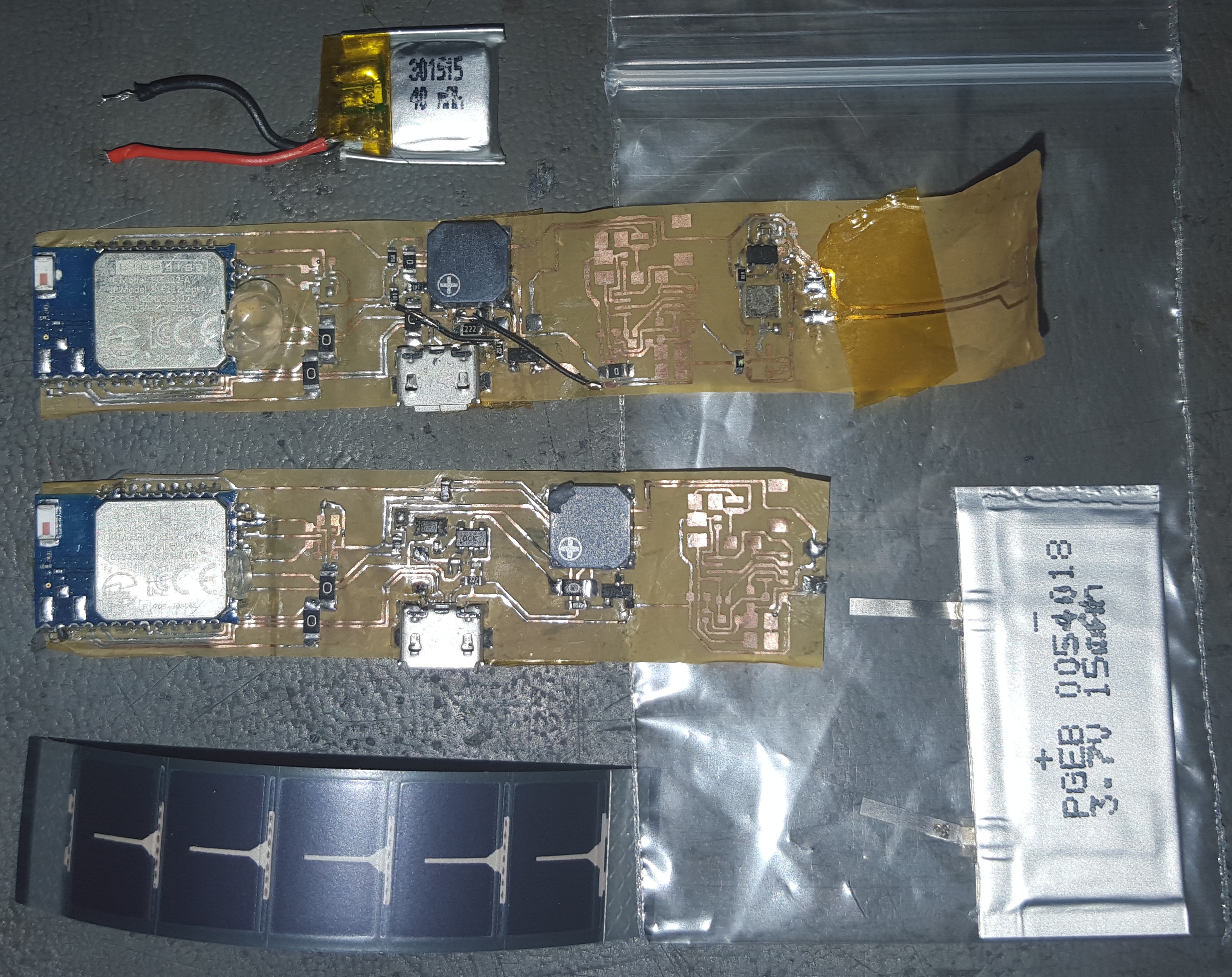
The 4th prototype design which I am waiting on parts for using a different solar charge circuit as well as on board battery protection. I also found some flexible LiPo batterys to use so the whole unit Batter+Solar cell +PCB will be able to conform to the shape of the cat collar. I also opted for the use of much smaller transistor packages as well as a Buzzer 1/4 the size of the previous one. The BLE radio was upgraded to the Long Range version to boost the detectable range of the collar.
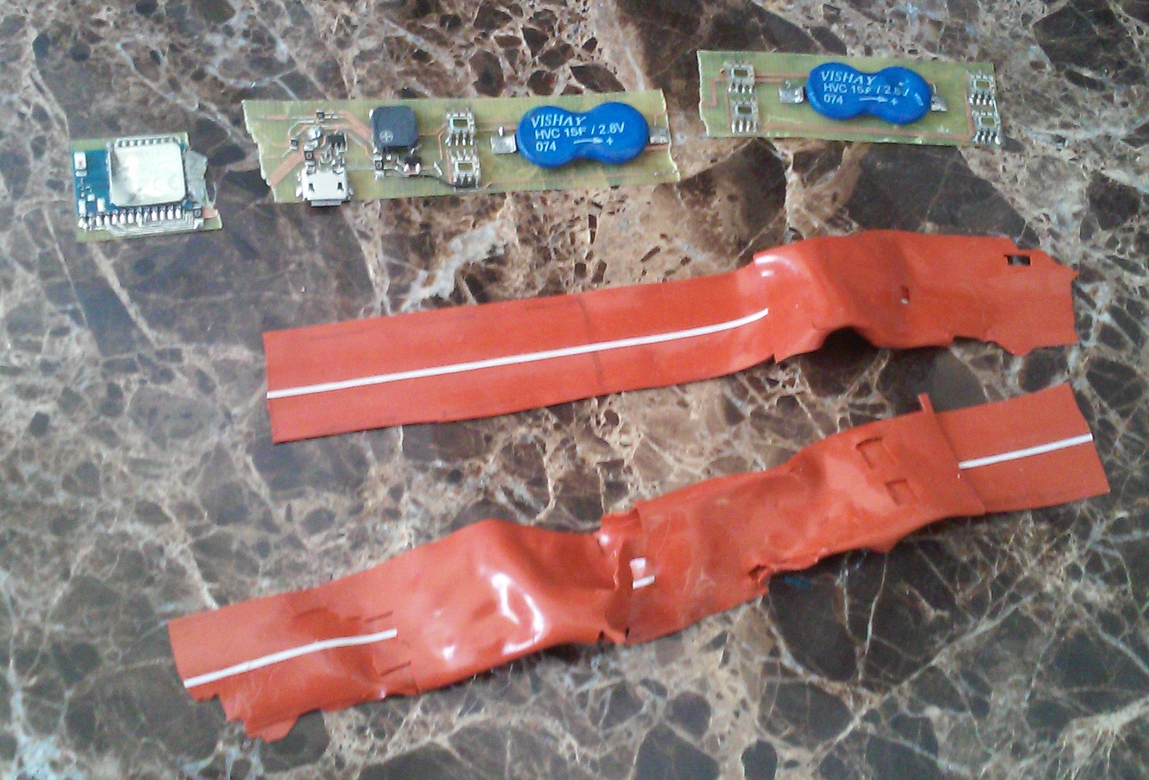
![The old uneaten prototypes sans batteries as well as the future, a flexible solar panel and flexible 0.5mm thick battery.]()
By the end of next week I will have the 4th and hopefully final prototype of the electronics board. For packaging I intend to print a flexible rubber case to fit over the components and meld with the battery and solar panel.
Sol BLE Tracker
Solar powered Bluetooth Low Energy Tracker with beeper and LED to assist in locating it.