 ben biles
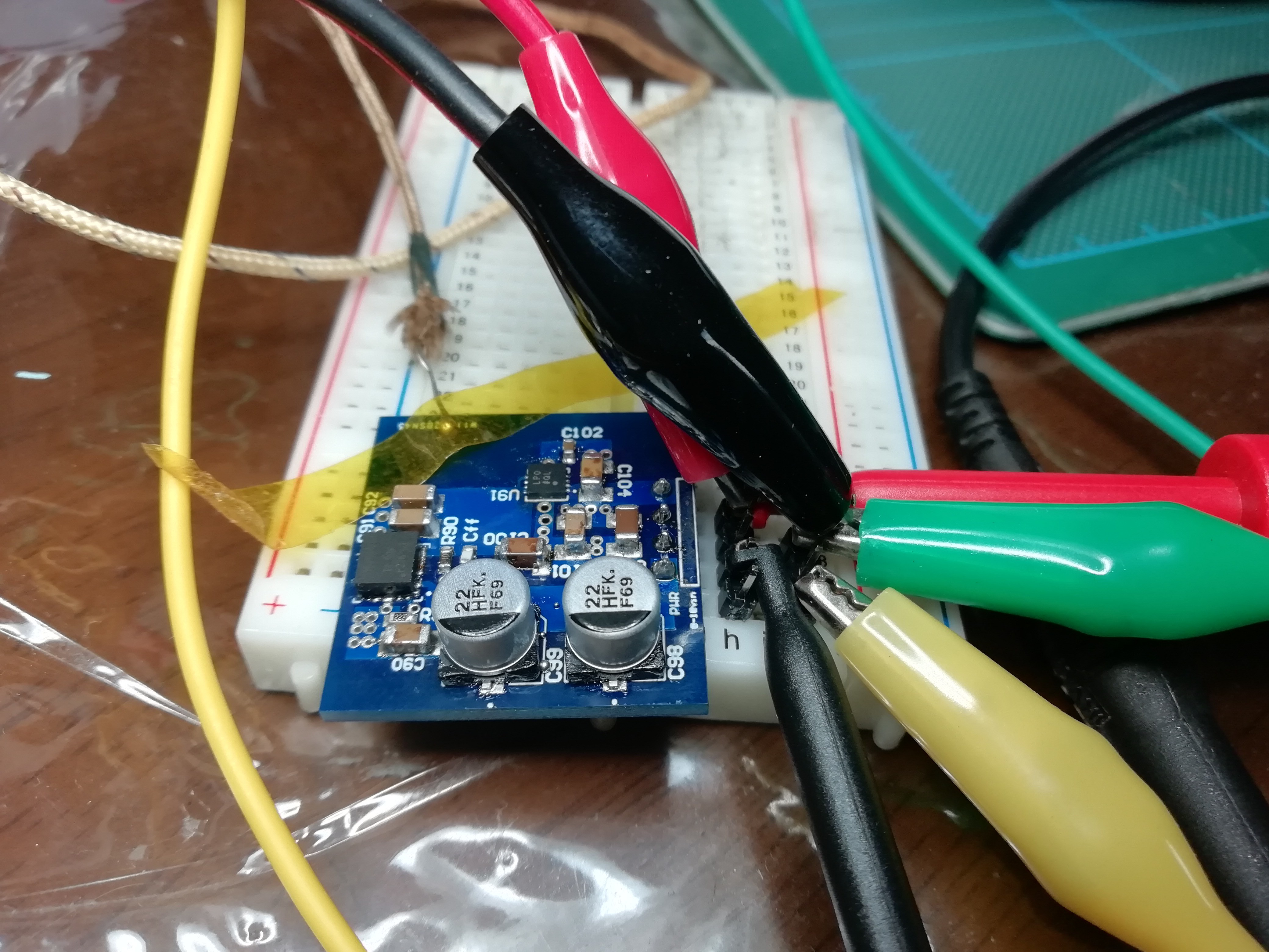
I just soldered up my new 3.3V 2A module and i'm running a test under load.
the board temp is about 50c - 55c after an hour. ambient room temp is about 26c
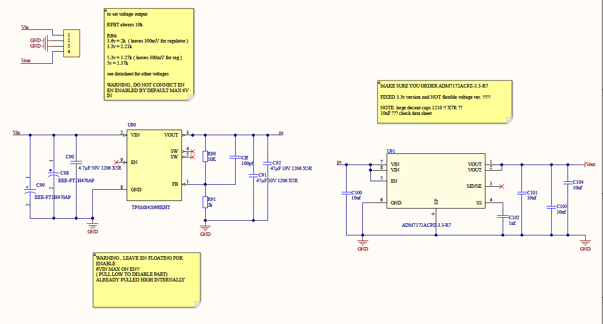
the TPSM84029 4.5V - 28V input
ADM7172 fixed 3.3V output ( should be ! )
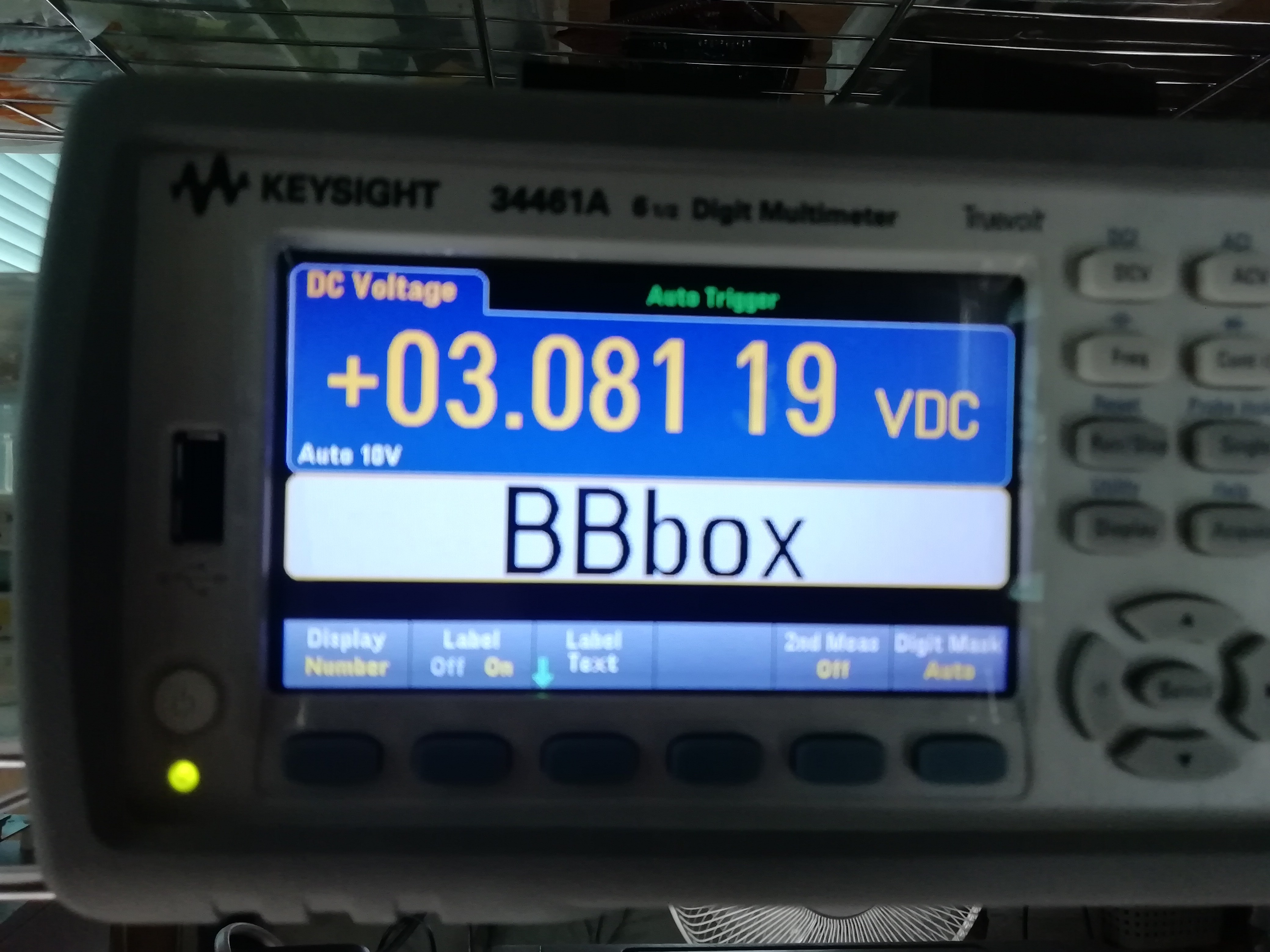
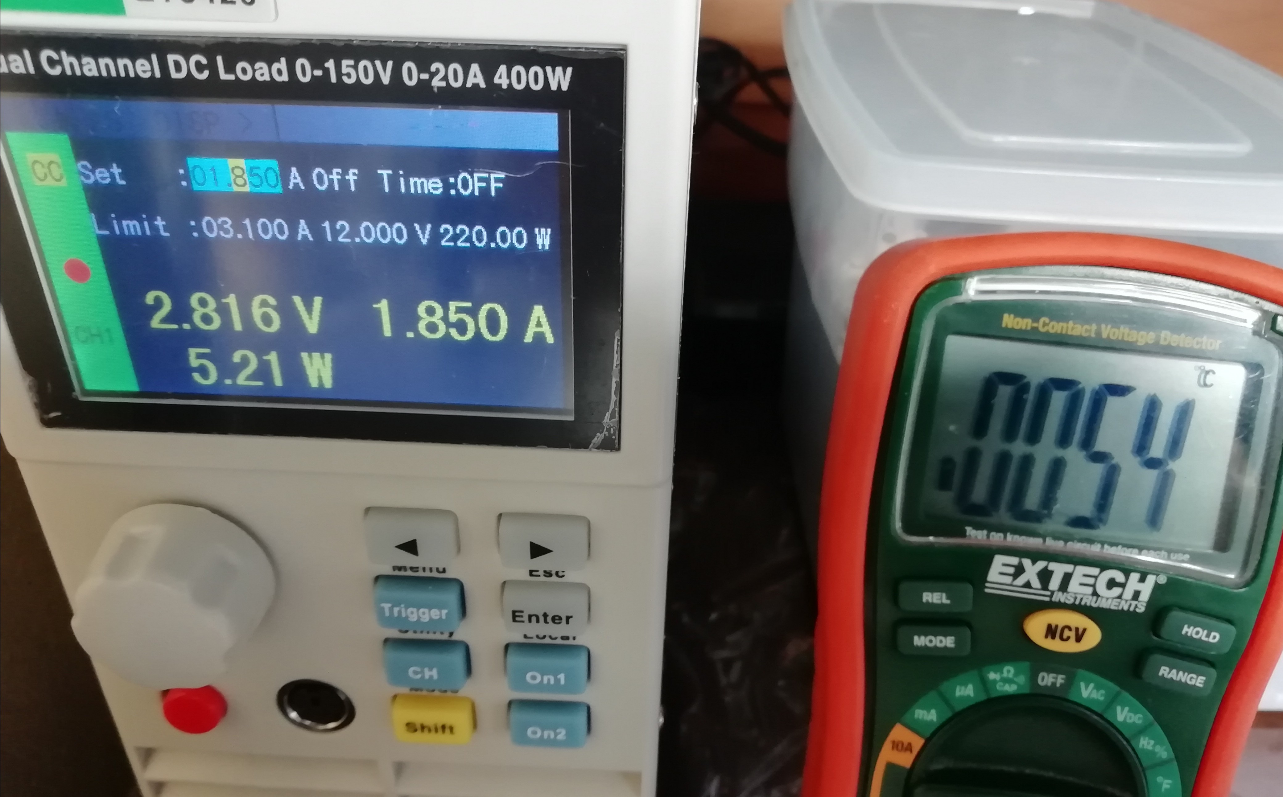
The dummy load is always a bit off so I hooked up my bench multimeter and noticed the voltage creeps down from 3.3 to 3v from around 1.25A load.
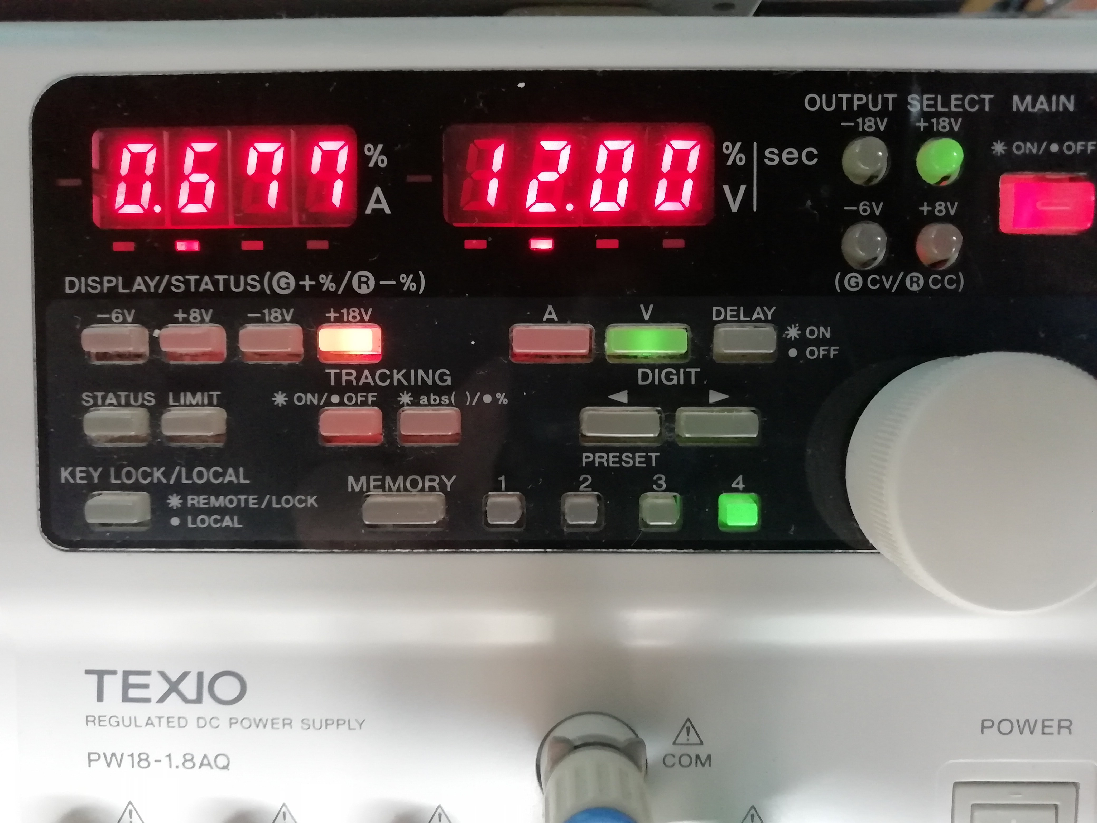
I'll never draw more current that around 1.2A and at startup only with the STM32H7 ADAU1467 and XMOS chip. but i'm interested in what can cause the voltage drop at the higher current draw?
at 1.25A 3.3V output 12Vin the board is at 40C
I really need to get an ESR meter I think to check the ESR of the input output capacitors.
Can anyone else see anything else wrong with my design ?
should I have more than 300mV headroom for the low noise LDO AD7172 ?
Could it even be at higher current loads multimeter test wires need to be shorter?
either way this module is way more stable than my last effort and totally usable in the design for now :)
Discussions
Become a Hackaday.io Member
Create an account to leave a comment. Already have an account? Log In.