 ben biles
I attenuated the 9vpp swing of the PGA2500 output to 4.5vpp for the ADC with one balanced U attenuator ( 3 x resistors ) 2 in series and one bridge resistor follow them.
I used oversized 47uhf 63WV capacitors ( same as DC blocking capacitors ) for the AC coupling capacitors. I'm sure they are overkill for the 2.5v DC bias on the ADC side but don't know how to calculate the proper value yet.
I already had ceramic AC coupling capacitors on the output of the PreAmp as PGA2500 is DC -650mv biased. so it went ...
Preamp output - 10uf 25v ceramic caps - U attenuation ( divide by 2 ) - 47 63WV electrolite caps.
Well for testing this worked out fine.
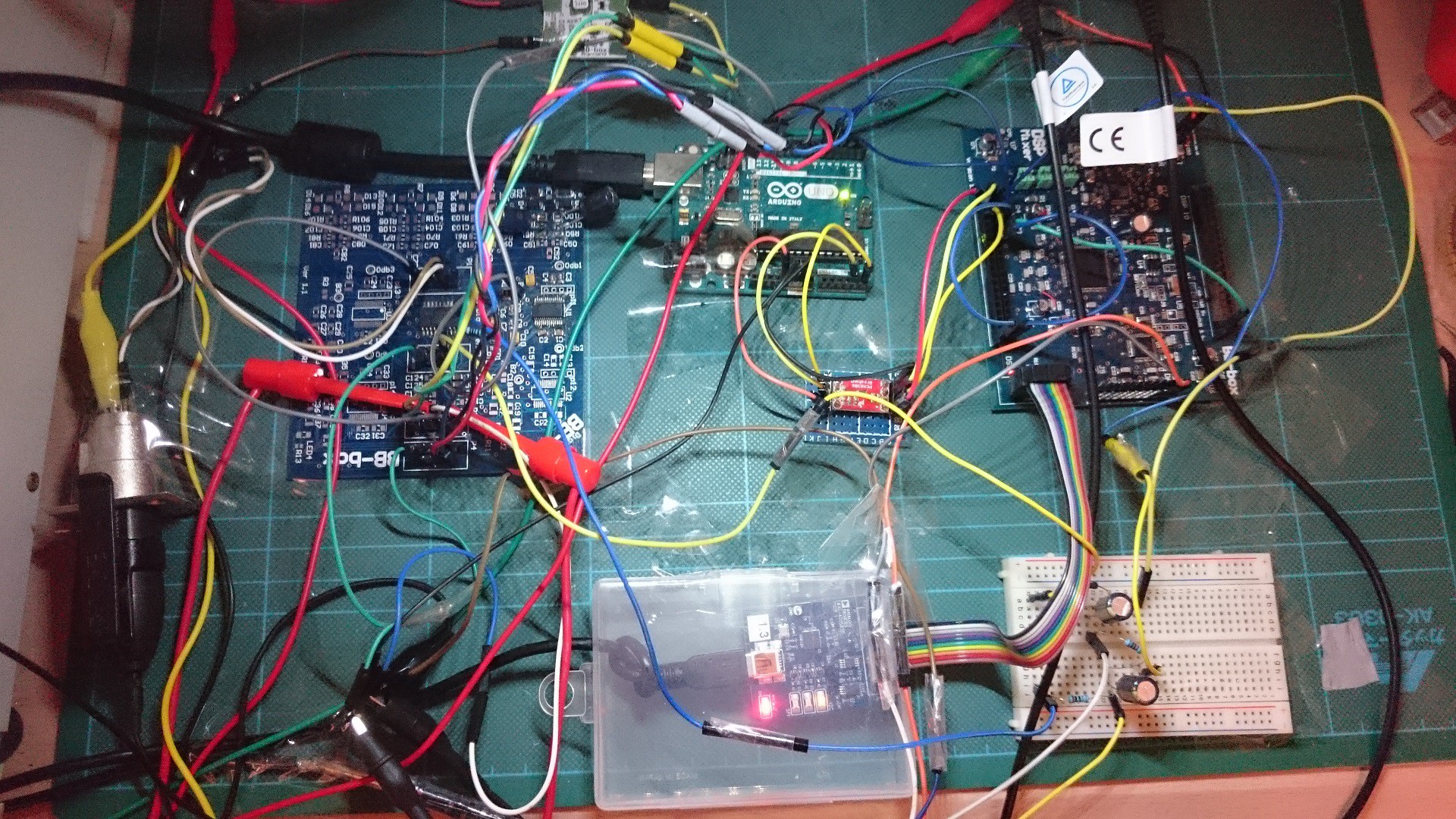
Top = 48v phantom power
left = 4 channel PGA2500 pre amp. ( only one channel populated and running for now )
Top Midlle = arduino Uno R3
middle midlle = I2C logic level translator 5v - 3.3v
bottom middle = USBi ad DSP programmer
right = 8 channel ADC / DSP / 8 channel DAC
bottom right = breadboard with single channel balanced U attenuation and AC coupling caps for ADC
There was very low noise , none from phantom power supply. The noise was more detectible if I used large compression in the DSP but still it was very low ! The next versions of trhe boards will include proper split ground planes and I2C / SPI isolator IC's
I need to decide if there is any point in using buffers to connect the preamp's to the ADC or if the AC coupling caps and resistor attenuation is enough. the Cirrus logic multichannel ADC has anti-aliasing filter in the IC.
Discussions
Become a Hackaday.io Member
Create an account to leave a comment. Already have an account? Log In.