03/03/18
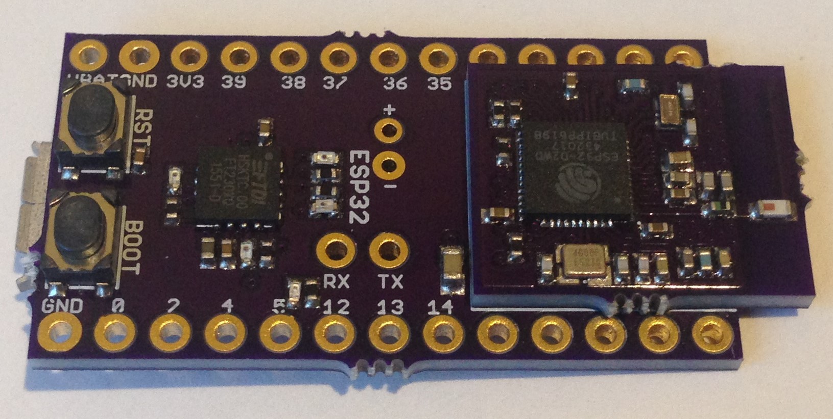
Phase 2 is assembling the module onto the acceptor board. Now this process is straightforward and I expect success in the sense that I will be able to actually solder it uneventfully. Here it is:

To my delight, I was able to flash the same blink program and get it to work the first time out. The battery voltage monitor on pin 34 seems to be reading too high, but the led blinks and I am reading the ESP32 chip temperature. Now to do some more testing in the next few days to compare the performance between the integrated board and the modular one. But overall, I declare victory!
Now if I choose to go ahead and have some modules made there are a couple of changes I would make. One is I would use an 0.8-mm-thick pcb to reduce the overall height of the module and make reflow easier. I would also insist that the module have straight edges instead of the somewhat ugly mousebite remnants that come with the OSH Park boards. I would add more ground vias to the ESP32 thermal pad to improve the heat sink and reduce the inductance between the board and IC. I would probably also add a thermal pad onto the acceptor board like the WROOM module for the same purpose.
I am not sure about the metal can. There are design houses that can make custom RF enclosures but I am not sure I want to incur the expense. Perhaps I will make one more design iteration to add the vias and thermal pad before I declare this modular design good enough. Some testing of the peripherals is in order as well while I wait for the design revision.
Somewhat to my surprise, it looks like this idea not only has merit but is cursed with working the very first time! Maybe I should quit while I am ahead...
 Kris Winer
Discussions
Become a Hackaday.io Member
Create an account to leave a comment. Already have an account? Log In.