Close
0%
0%

3D Printed Electric Spinning Wheel

Sometimes you don't want to pay $1000 for a spinning wheel. Sometimes you want to just print one. Now is that time, for me.

Similar projects worth following
This project aims to create a 3d printed electric spinning wheel. Pretty self explanatory, really.

Some decisions I've maybe made:

1. Motor and Electronics will be mostly enclosed

2. Will use a belt (silicone tubing), driving the spool. The pulley will be attached to the spool end. I may have to add some sort of belt tensioner, not really sure yet. 2:1 drive-gear;pulley ratio. This should allow for 4.5-5k rpm speeds, which is pretty fast for a spinner. Maybe too fast for this thing.

3. Both spool ends will have pushfit printed geared bearings (fallback plan is to print bushings for 608 to fit)

4. The brake will be around the flyer's shaft. There will be a knob in the front panel that allows one to adjust the scotch brake.

5. The flyer will be in a geared bearing. Working on the details of this part (such that the spool is easily removable). The threaded metal rod will be attached directly to the flyer. Its other end will be, of course, in a geared bearing.

6. Somewhat trapezoidal threaded-rod and printed plastic frame.

Version 2:

Add BMS/PCM circuit with a lifepo4 battery at 14.4v and make it mobile.

Version 3:

Add NC socket w/ 3dp foot-pedal thing to pause spinner temporarily.

  • 1 × 12V DC Motor 12 Volt DC Electric Motor 1/35HP 2350 RPM Ametek CCC-0038 (Dayton 2M197, 3LCH7)
  • 1 × 12V 6A Power Adapter
  • 1 × PWM Motor Controller RioRand Upgraded RRCCMHCNSPC PLC 6V-90V 15A 1000W Pulse Width PWM DC Motor Speed Regulation Controller
  • 1 × Toggle Switch Toggle Switch Center-Off 20AMP EC-1520 DPDT-CO ON-OFF-ON
  • 1 × 4S LiFePo4 Battery Pack (optional/planned) ZIPPY Flightmax 4200mAh 4S1P 30C LiFePo4 Pack

View all 7 components

  • Non chronological post!

    firebovine08/21/2015 at 04:51 0 comments

    I forgot to provide an update regarding my earlier endeavors. I received my super-beefy-for-no-reason-at-all DPDT switches. So I soldered up the electronics and now have a working forwards/backwards 1/35th HP DC motor. It already has a flat shaft, so that's nice. For now I will consider the electronics done, as I work on the mechanical aspects of the design.

    For the future:

    There is a feature in other high end electric spinners which allow a foot-pedal to be connected to act as a quick-stop. I am not entirely 100% sure how to do this circuit. I don't really want the current going to the motor to have to go through the foot-pedal. Connecting a Normally-Closed socket in-between the motor and switch seems like it would work, it doesn't seem like a great idea as the motor is quite powerful, and the foot-pedal will be hand-made. I would rather somehow manipulate the potentiometer on the motor controller when the foot-pedal is plugged in. I don't really know how to do that, but I'll probably wade through documentation and figure it out later. If you have an idea, please leave a comment.

  • Finally, the first of many geared bearings.

    firebovine08/21/2015 at 04:41 0 comments

    Captain's Log:

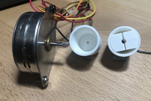
    I've successfully printed a 10-planet/large star bearing. I've also printed a spool end. I have shoved the bearing into the spool end, applied copious amounts of thick silicone lubricant (I use this to reduce friction/prevent friction-welding of parts with the pullcopter, so I figure it'll do). I then spun it with my drill a bit. While it still has quite a bit of friction, I believe it'll do fine. If not, we'll replace it with a 608. I will try to keep this design easily adjustable to use 608s because I have noticed these geared bearings make quite a bit of noise, even at low RPM. Fortunately, it's a good plastic gear crunching sound, which everyone loves.

    I've also finished prototyping the shaft. It'll be comprised of two 70mm lengths that get glued. I will probably use epoxy. Although the spool end, and of course the bearing, were printed in PLA, I may print the shaft in ABS. The reason for this is so I can sand the top surface to be very smooth, to make a good joint surface. PLA can be iffy on the sanding, and my printer can be iffy on the precise calibration.

    I've also finished prototyping a simple coupler to join the spool to the shaft. This allows the outside of the bearing/spool to be affixed to the spool-shaft, while allowing the threaded rod to go through the center of the bearing and shaft. I believe it will require support when printing, but the ugly side will be hidden.

  • It Begins....

    firebovine08/13/2015 at 05:11 0 comments

    At this point I only have ideas, drawings, and some roving.

View all 3 project logs

Enjoy this project?

Share

Discussions

Similar Projects

Does this project spark your interest?

Become a member to follow this project and never miss any updates