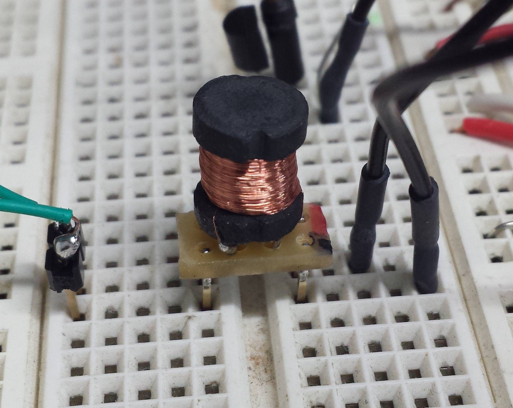
The mystery part was identified as a transformer.

When it was removed from the original PCB one of the enamel wires came loose from the case pin. This resulted in an intermittent/partial connection and a lot of frustration during testing. This was fixed with an extra glob of solder.
An MSP4302353 replaced the G2211 in the breadboard. The G2211 only has one timer, plan on using two timers to control frequency and length of the chirp. Speaker operation was tested from 100 Hz to 10 kHz with 50% duty cycle. NPN BJT was used for high side switch. The original device used a low side switch. Volume was adequate through most of the range, started to drop off around 8 kHz. Going to proceed with the design re-using the transformer from the window alarm.
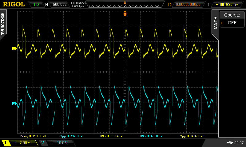
The RMS voltage ratio seemed to be consistently between 5:1 and 6:1.

 mulcmu
Discussions
Become a Hackaday.io Member
Create an account to leave a comment. Already have an account? Log In.