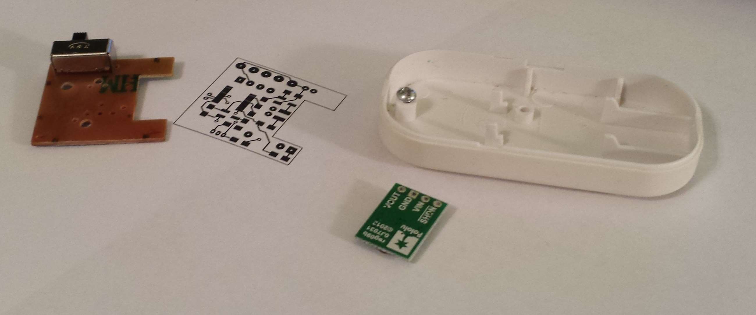
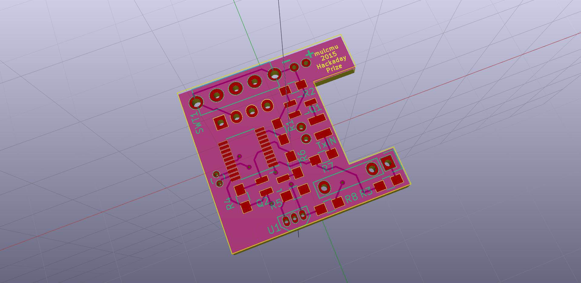
Finished the PCB layout. The Pololu regulator will be mounted under the main PCB. There is a plastic stand off that will need to be removed for clearance. There was a corresponding hole on the PCB to secure it to the case but none of the ones I've opened so far have been screwed down. Other layout options got the module too close to the supports around the edge of the case.
The speaker drive transistor was changed from a NPN BJT to a n-Mosfet, 2N7002. Almost got burned by the SMD package pin numbers being different than the TO-92 case pinout. I left the base resistor in the design to support going back to BJT. Initial testing with the 2N7000 was a bit louder on the volume. A series resistor was added with the transformer input to cut the volume down a bit.
Added the battery voltage monitor back into the design. The resistor divider for the ADC input is also controlled by a 2N7000 to minimize standby current consumption.
Forgot to add in a footprint for the SMD hall effect sensor, those will have to wait until revision 2.


 mulcmu
Discussions
Become a Hackaday.io Member
Create an account to leave a comment. Already have an account? Log In.