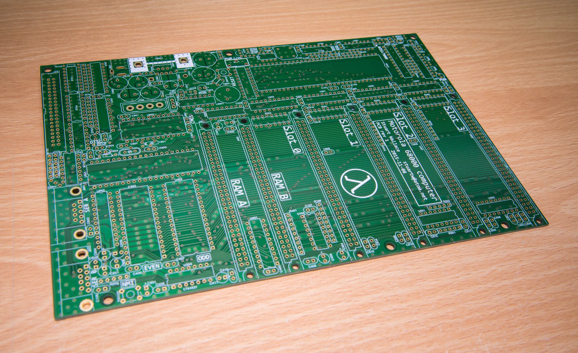
I'm about to start assembling the first revision of the Motorola 68000 motherboard. This revision, rev1 (I start my revisions at rev0), includes a few fixes for minor problems in the prototype. None of these problems were show-stoppers, and I was able to craft fixes where necessary in order to get the rev0 (prototype) motherboard working. More importantly, rev1 adds some minor new features to the board. Here it is.

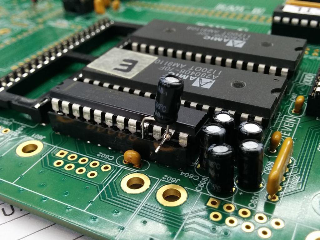
Here's an example of a rev0 bug I needed to fix. This is my hacky fix for a wiring error in the capacitor network which the MAX238 RS232 driver/receiver IC uses to drive its internal voltage converters...

The second revision fixes these bugs in the prototype:
- The aforementioned capacitor cock-up;
- A schematic error led to me using the wrong set of outputs on a glue logic IC;
- I misread the ATA/ATAPI specification, and treated the ATA interrupt line as active-low; actually it's active-high;
- Each expansion slot can assert a separate interrupt input on the CPU. One of the slots, Slot 3, was wired (intentionally) to the CPU's non-maskable interrupt (NMI) input. This was an idiotic decision.
A few other, more cosmetic, problems are also fixed in rev1:
- Some component footprints have incorrect hole sizes or lead pitch;
- Some parts slightly fouled on adjacent components, making assembly tricky;
- The footprint for the RTC backup battery was just... wrong;
- Some silkscreen text was obscured by holes and other components;
- I've done some work optimising the PCB's power distribution and grounding. I hope this will result in lower RFI emissions - I'll test this with the spectrum analyser at some point.
New features in rev1 include
- Shared interrupts: the four expansion slots now share two interrupt lines, instead of having one dedicated interrupt input per slot. This frees up a couple of interrupt inputs for...
- An NMI push-button: will be useful for forcing the system into "debug" mode;
- The real-time clock (RTC) IC's interrupt-request line was not connected in rev0, as I didn't think I needed it. Timer interrupts were generated by the MC68681 DUART. In rev1, the RTC can generate interrupts. This will be useful for generating more accurate real-time interrupts.
- I'm using a socketed RTC battery (on PCs, this is known as the "CMOS backup battery"), instead of a battery soldered to the motherboard. This will make it easier to replace the battery.
So: I'm about to start populating the board. The last one took about 8 hours to solder; this one should be quicker, as I will be doing a lot less testing as I go along. I also won't be socketing all the ICs this time around; I'm only going to socket the expensive ones.
Wish me luck...
 Stuart
Discussions
Become a Hackaday.io Member
Create an account to leave a comment. Already have an account? Log In.