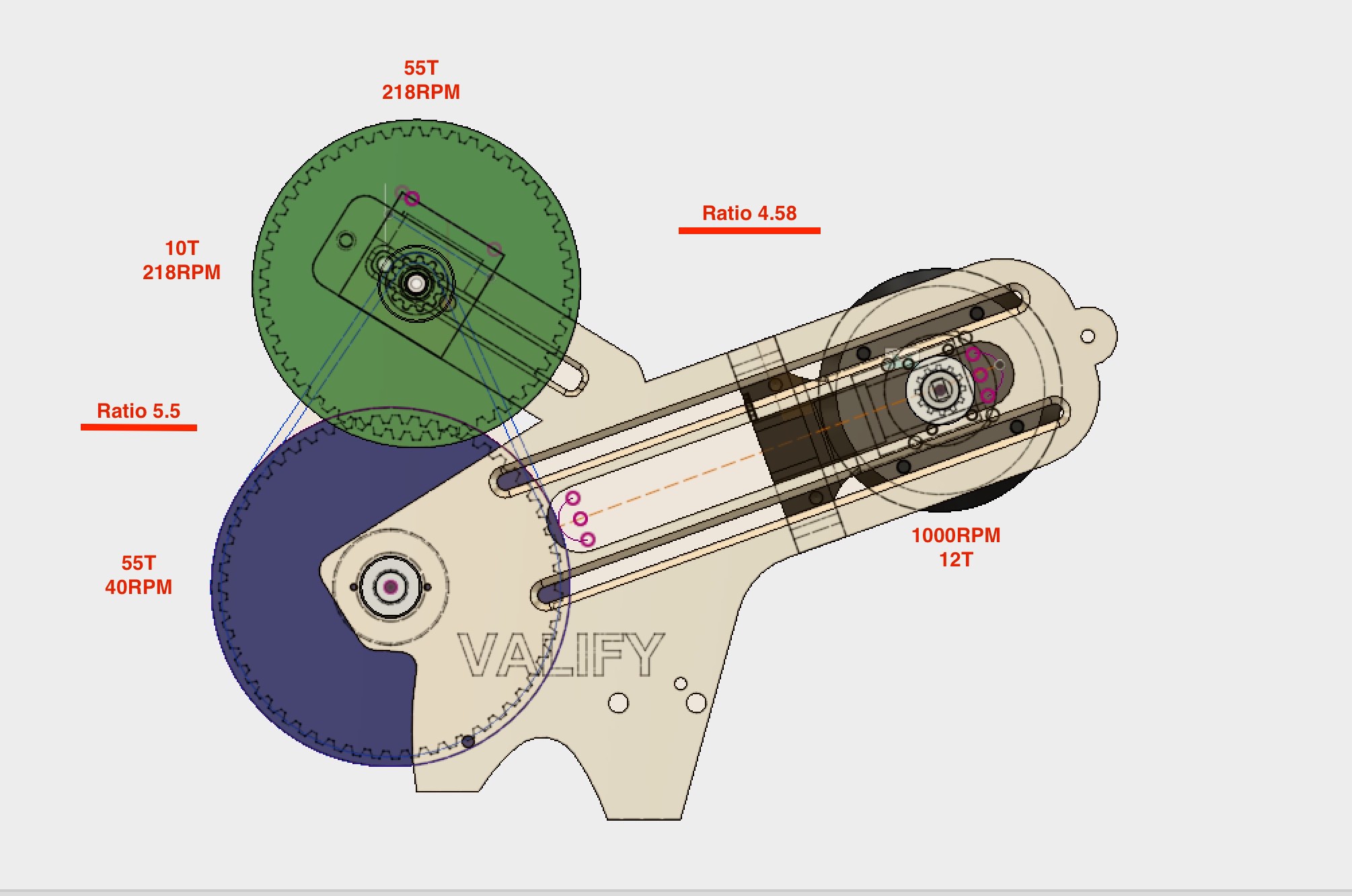
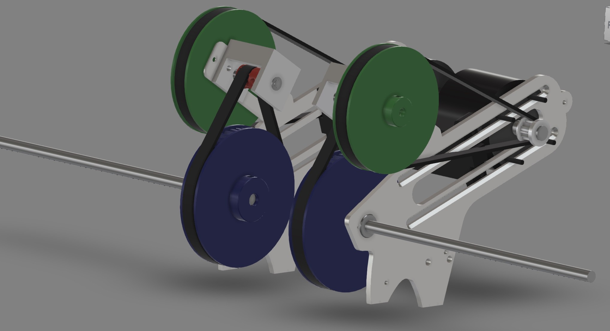
So this weekended I have been working on finishing the design of the drive system. I have updated the initial design of the 2-pulley gearing into a 4-pulley gearing. The main reason for the update is to have the ability the to achieve a lower wheel surface speed. The brackets are also designed with adjustable offsets, so each component can be adjusted to tighten the belt, or allowing a easy change off pulley sizes without redoing brackets.

My goal is a 0.4m/s wheel surface speed. Would give me 0.4*60/0.7225=33 RPM on the wheel shaft. So I am within the limits to achieve that. So this is the final design of the drive system.

Hopefully this week, CNC milling of motor brackets begins.
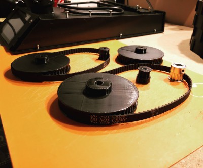
In the meantime I keep the printer busy with printing pulleys.
Sizes printed today is XL 10T, 50T and a 55T. Took a few test prints before I could find the sweet spot for the settings for a maximum belt grip.

 Robin Fröjd
Discussions
Become a Hackaday.io Member
Create an account to leave a comment. Already have an account? Log In.