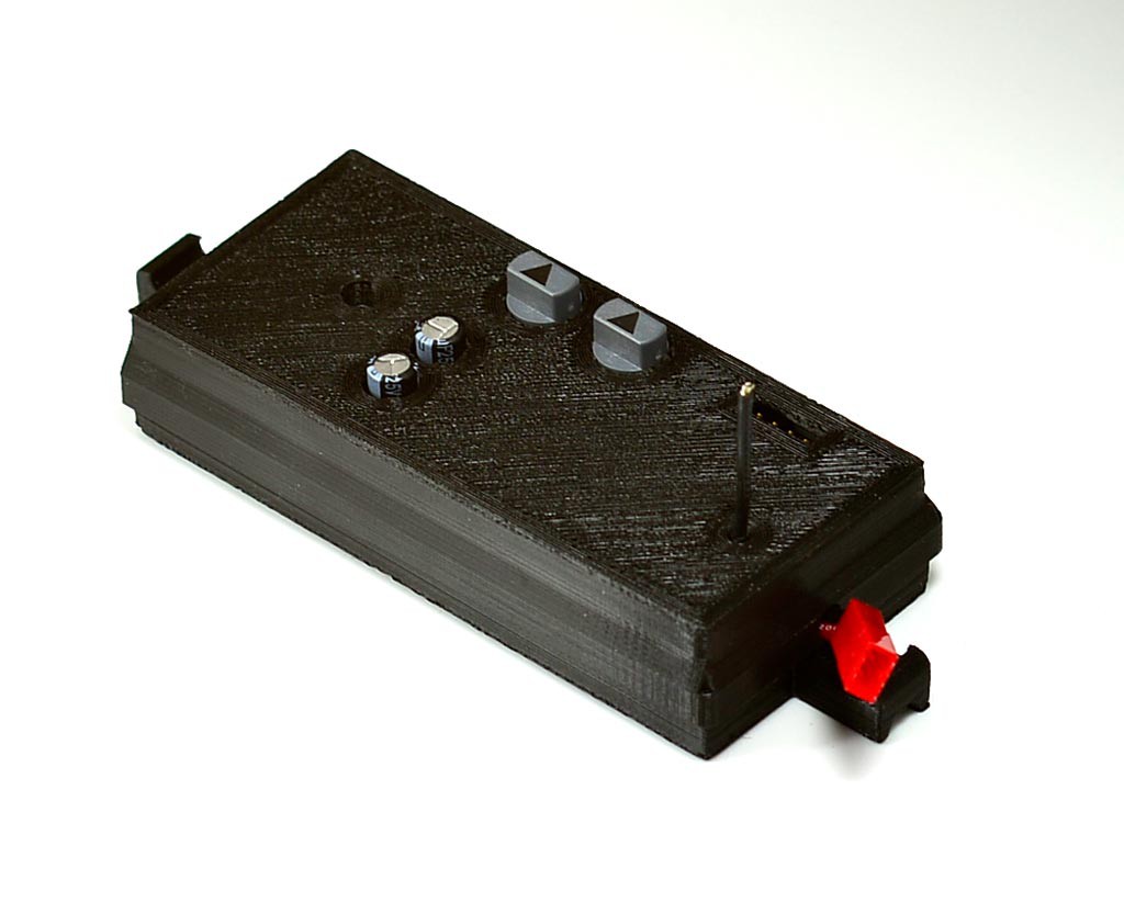
Here is a closeup of the completed Kite Light controller. You can see the two rotary encoders used to set the device address/default color and the default program. Two caps for the power supply that stick thru the case , the antenna for the XBEE radio and a 4 pin header that allows me to update the firmware without opening the case.

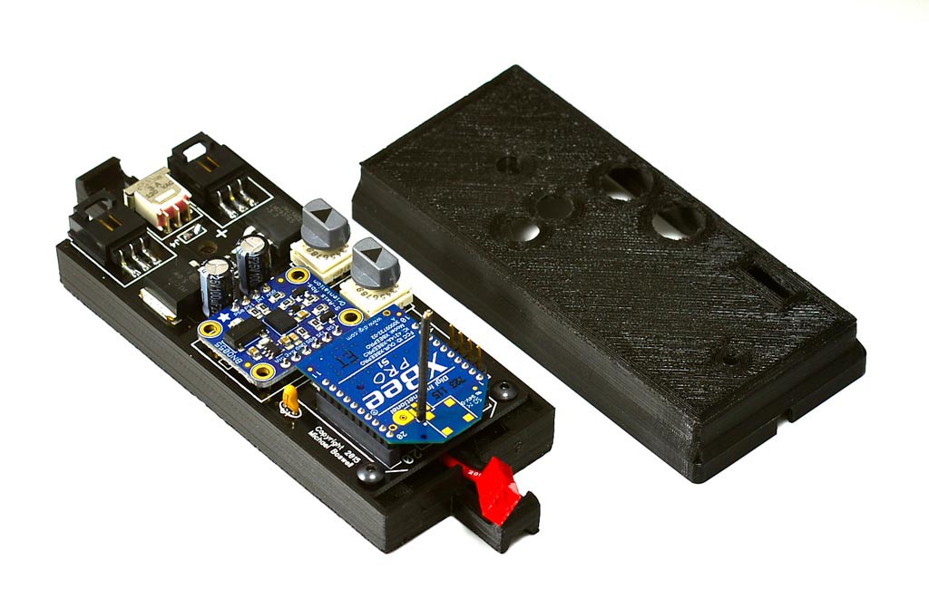
Here is another picture with the Case top removed. You can see the XBEE radio and the BNO055 absolute 9DOF position sensor from Adafruit.

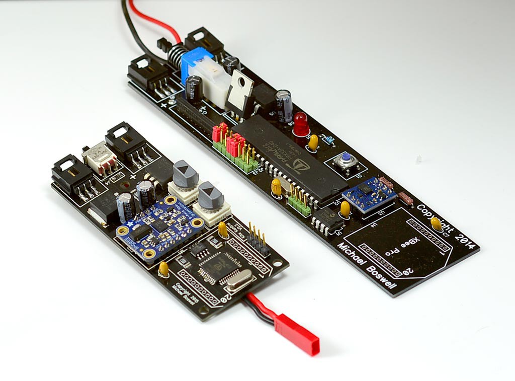
I tend to design and build things using a successive approximation method. The board on the Upper right is V1. V2 is on the bottom left and you can see the evolution in component choices such as the on/off switch, the programming headers and of course the move to using Surface Mount for some of the components. The Size reduction was almost 50%.

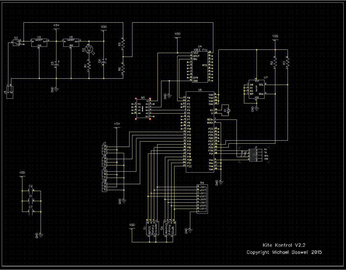
What project would be complete without showing the schematic. Actually quite simple. This project is more about selecting the best components and also learning to use a toaster oven to reflow-solder surface mount components.
 Michael
Discussions
Become a Hackaday.io Member
Create an account to leave a comment. Already have an account? Log In.