The designs for the balancing test base were done in Solidworks and exported to .dxf files. These were then brought out for laser cutting. Instead of acrylic, plexiglas (also a type of acrylic) was used. We found that plexiglas is more flexible and stands up the rigor of drilling without cracking.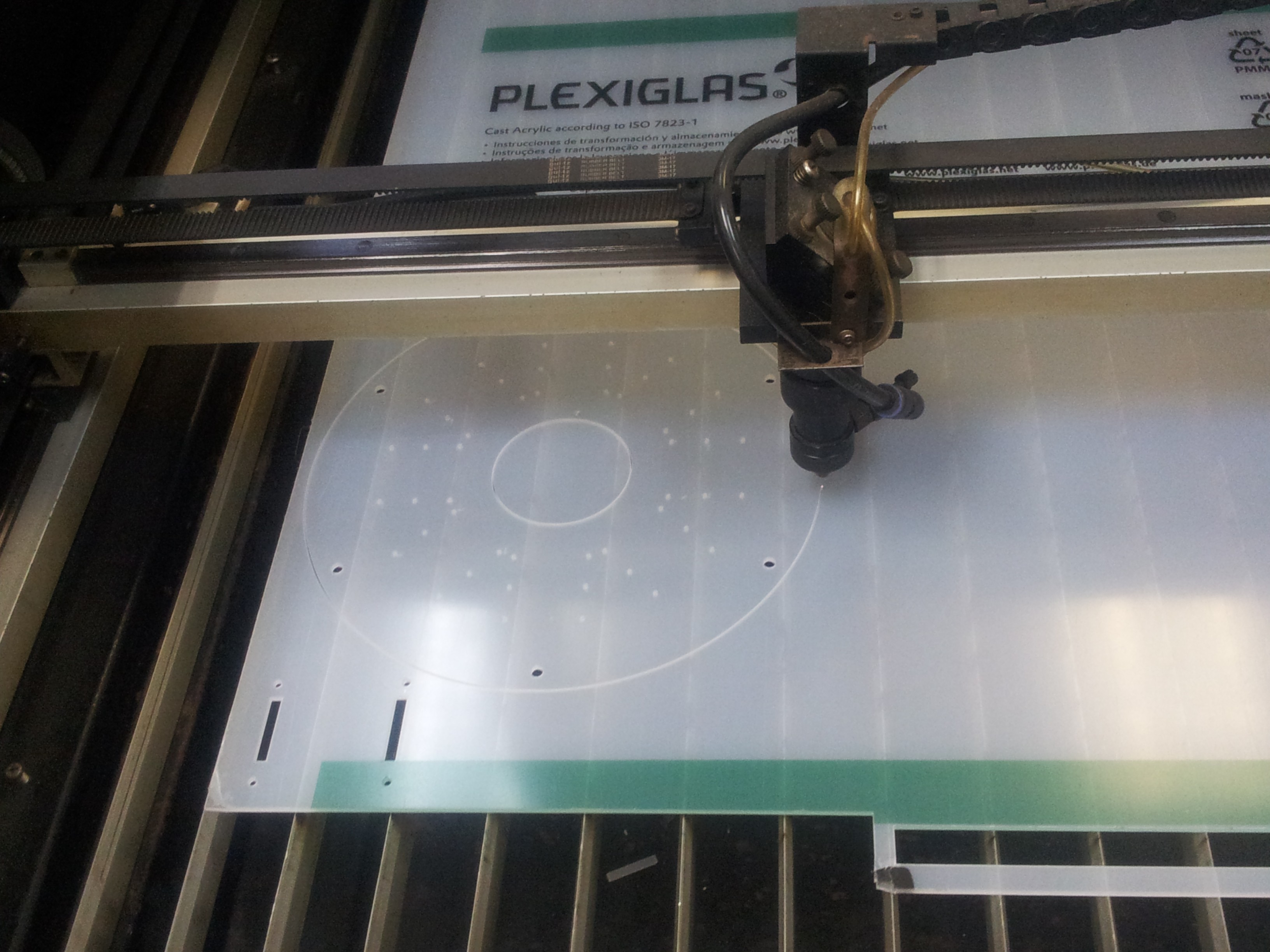
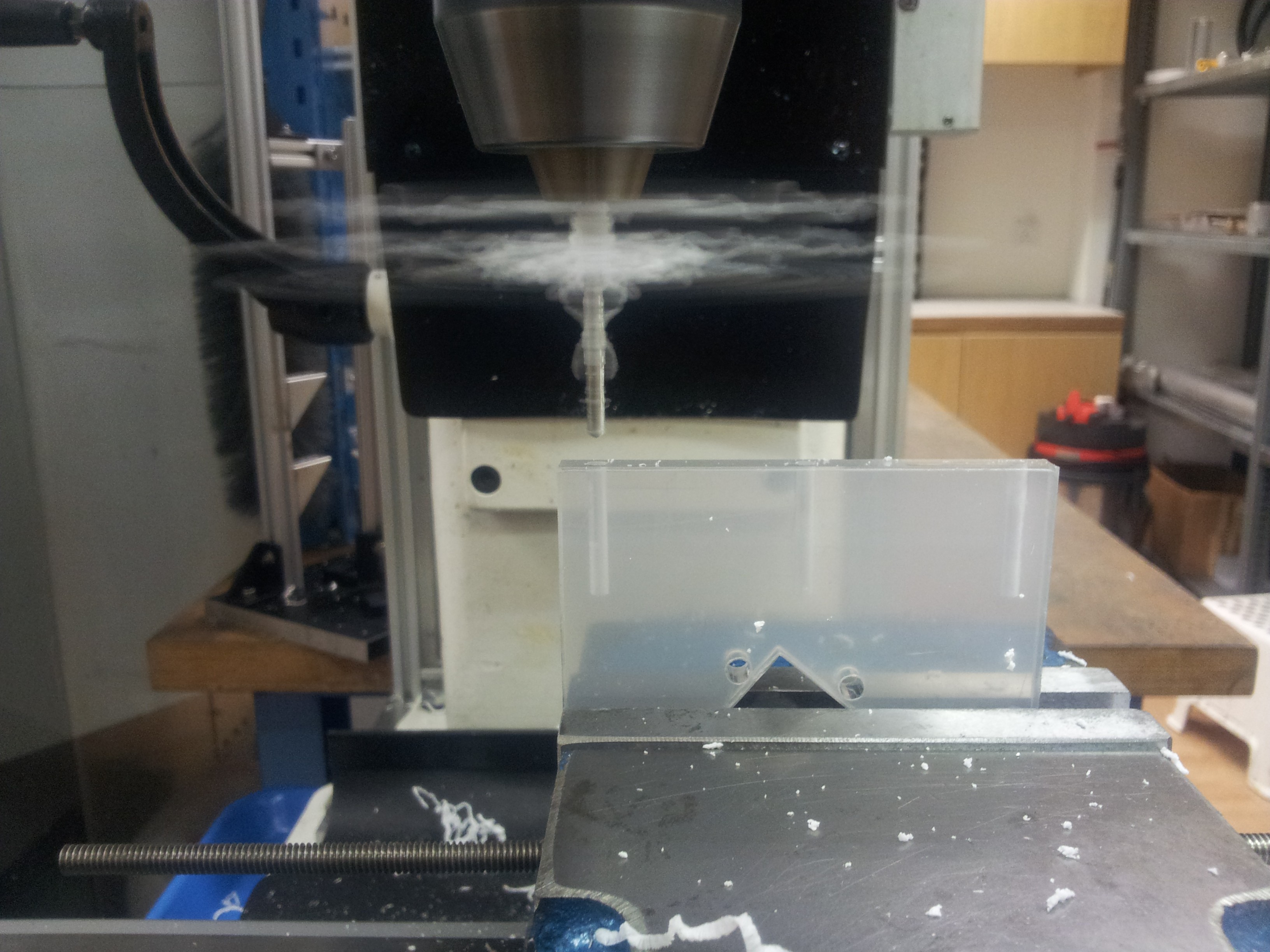
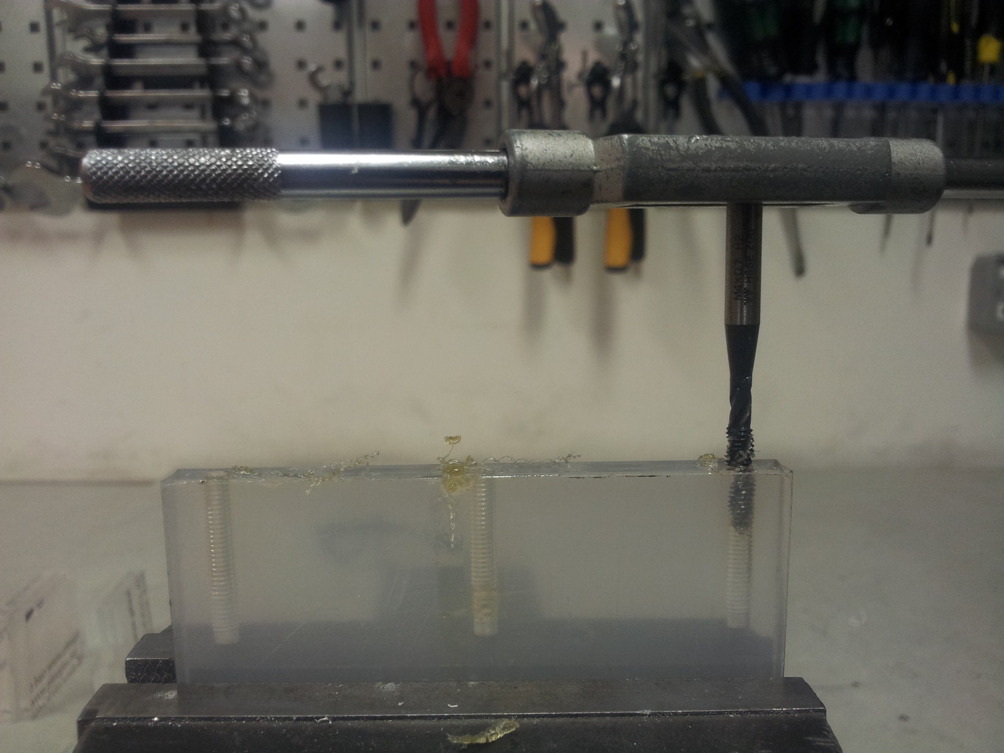
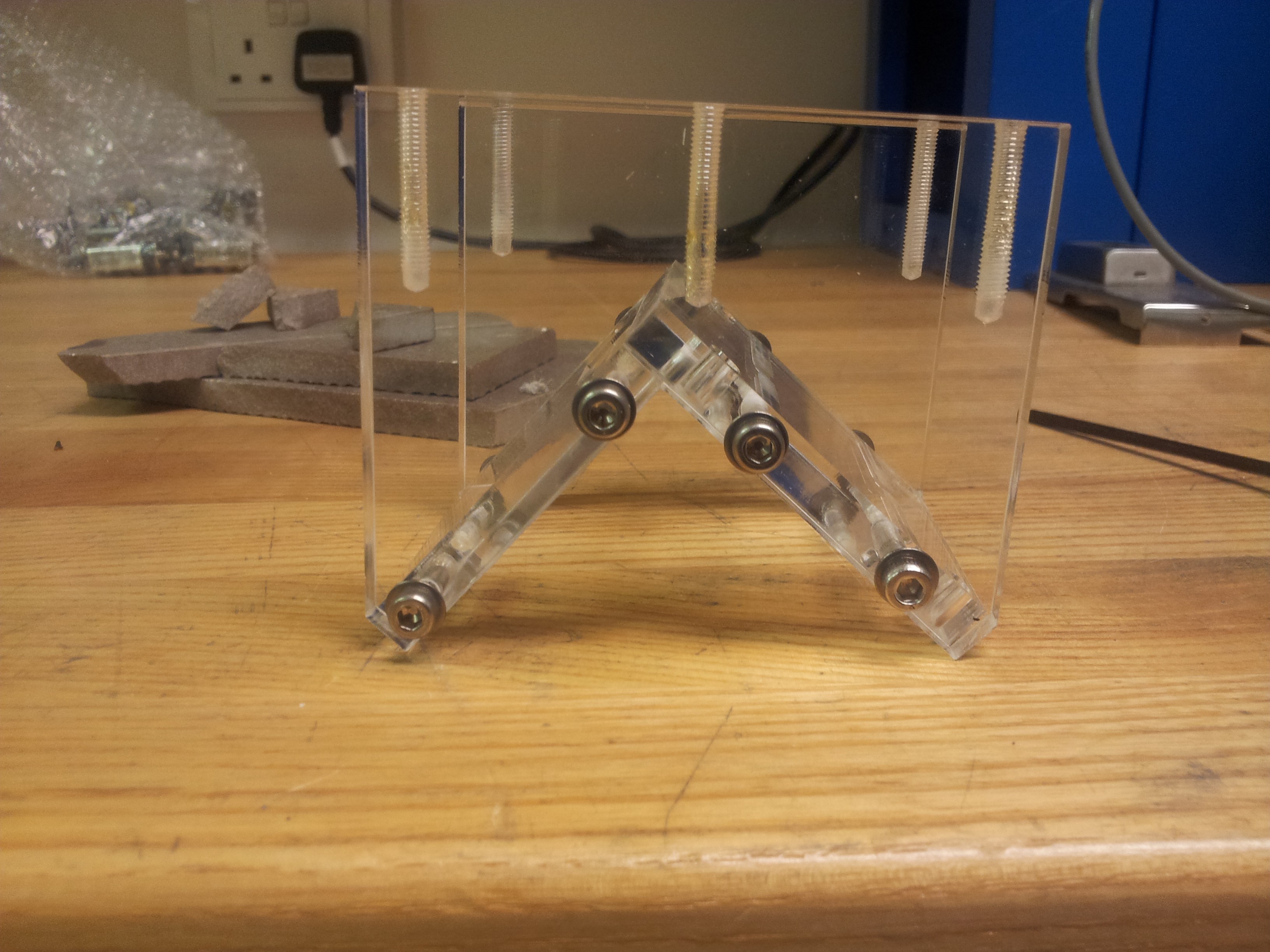
With all the pieces back from the laser cutter, we begin the ardous task of drilling all the holes for securing the mount for the stepper motor. Holes of 3.5mm diameter were drilled and tapped for M4 screws.
The spacers were cut to the appropriate length using a lathe. The central hole in the wheel hub for the holomonic wheels where also enlarged to 1/4" to accommodate the stepper motor shaft. The wheels were then installed onto the motor shaft.
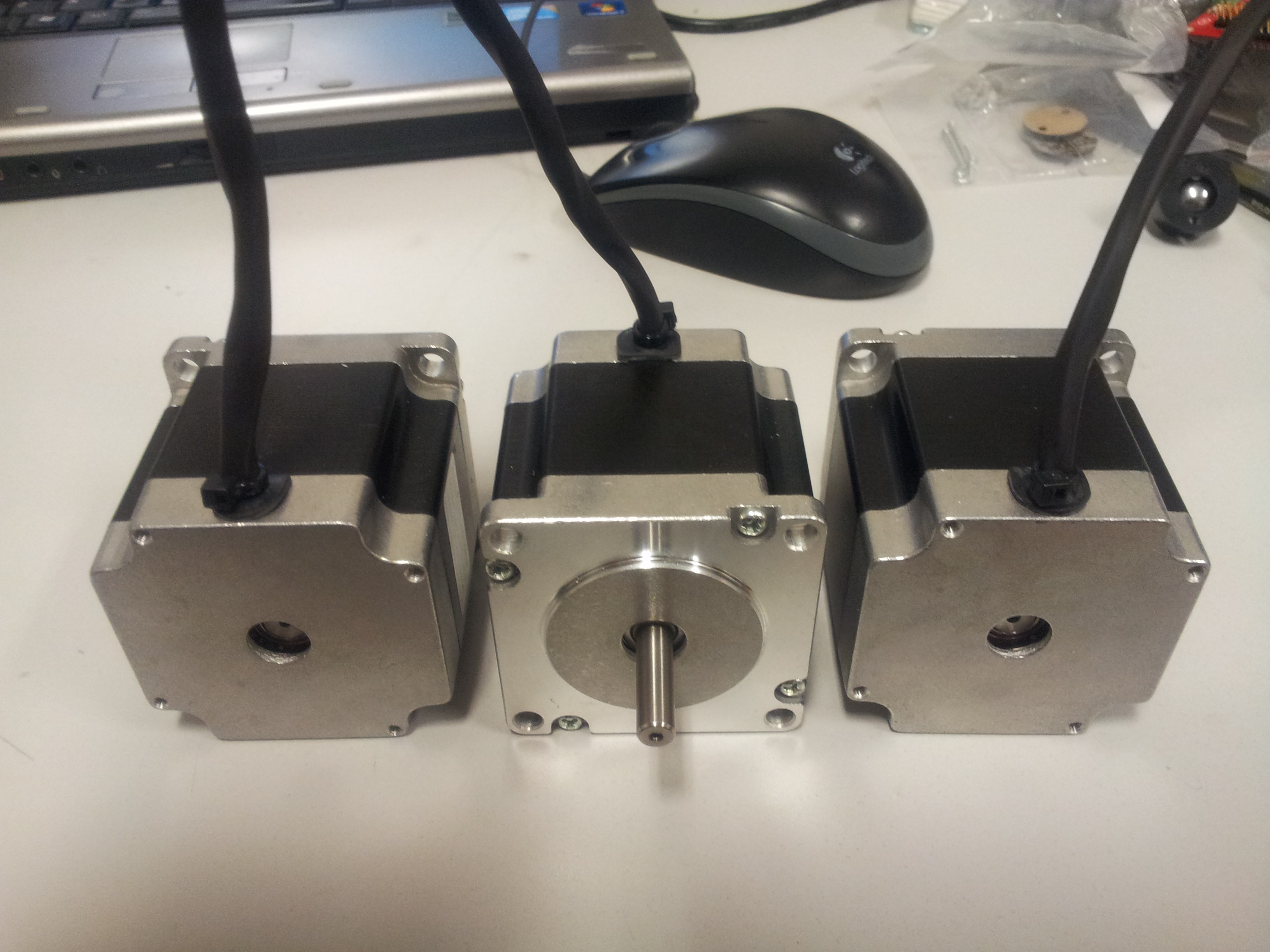
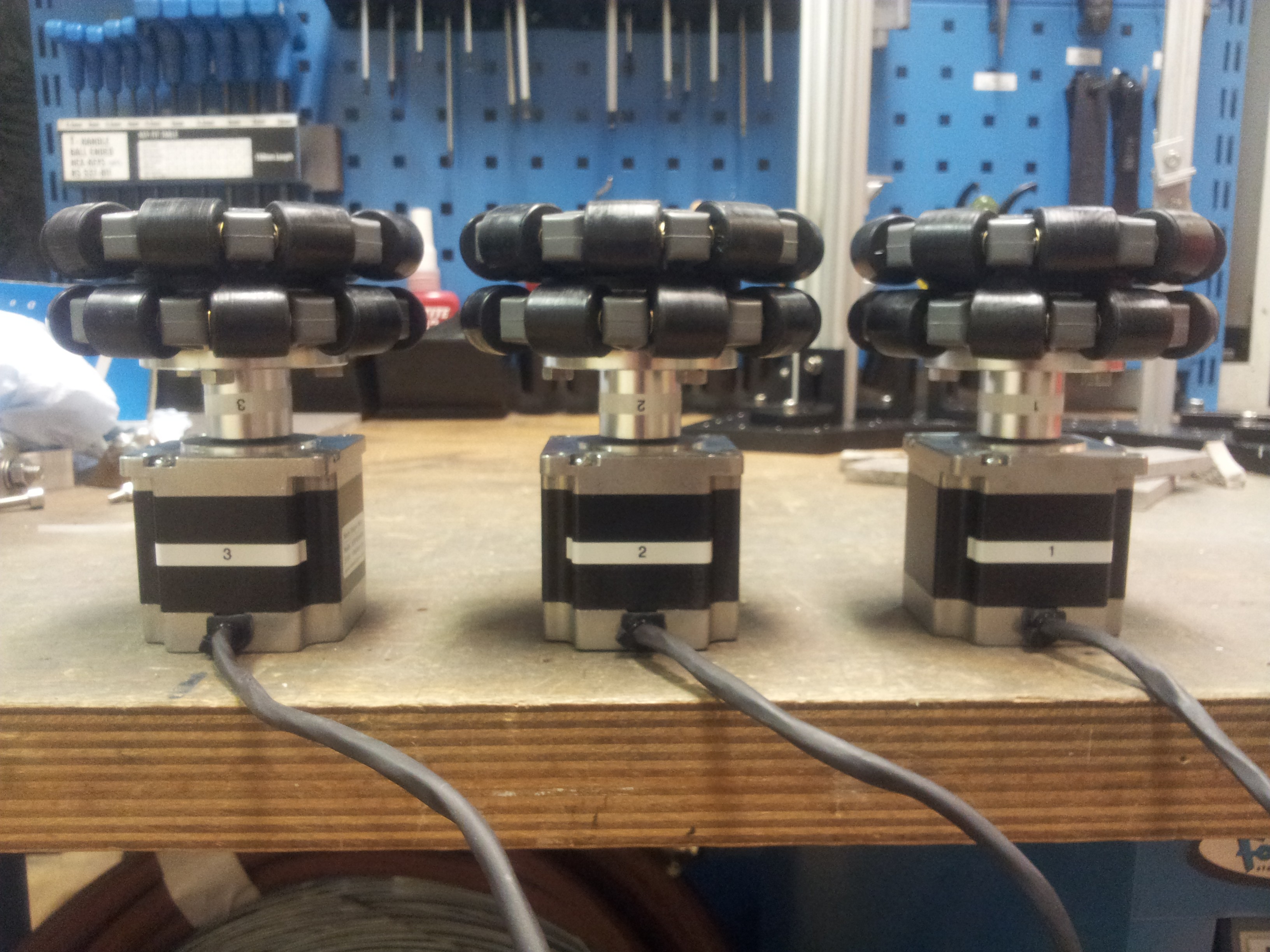
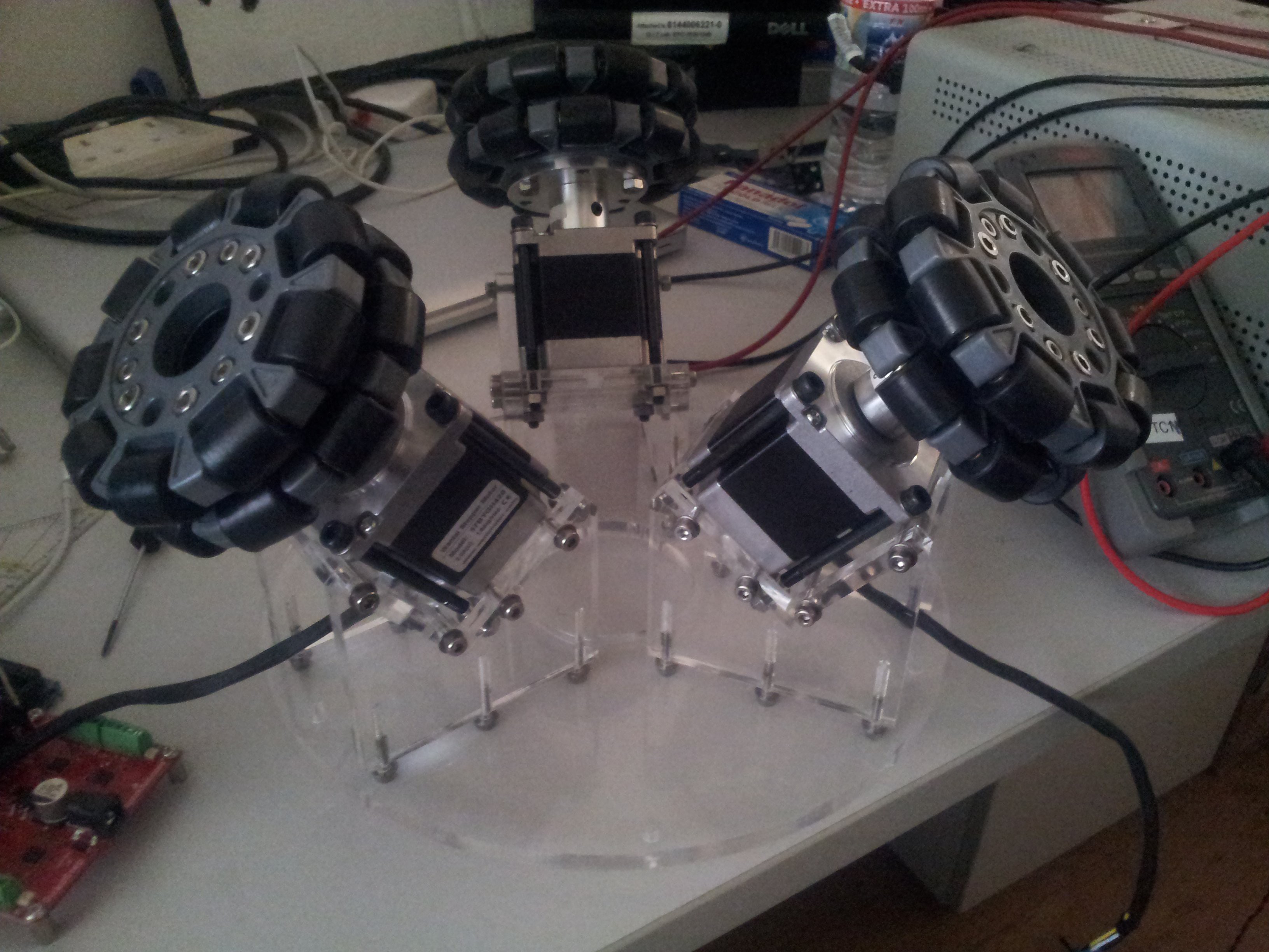
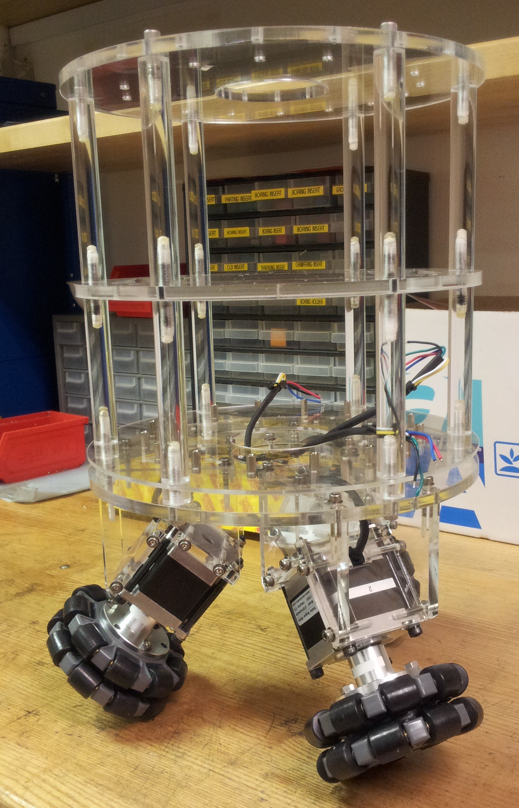
Finally all the parts were assembled.
Discussions
Become a Hackaday.io Member
Create an account to leave a comment. Already have an account? Log In.