Antti Easy Hacks
Collection of really simple hacks of mine
Collection of really simple hacks of mine
To make the experience fit your profile, pick a username and tell us what interests you.
We found and based on your interests.
Hey my UART is not working. The engineer looks at his microcontroller board or even worse FPGA board.
How many times I have heard it.
UART we have a problem..

This is generic way to troubleshoot RS232C UART problem.
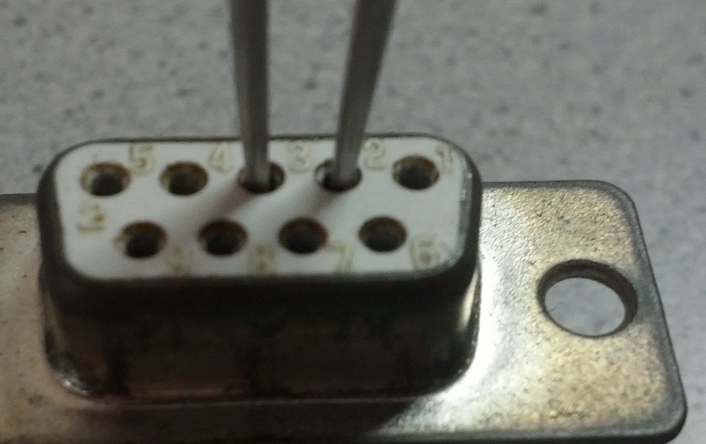
It is called loopback: you take tweazers, and short pins 2-3 creating a TXD to RXD loopback.

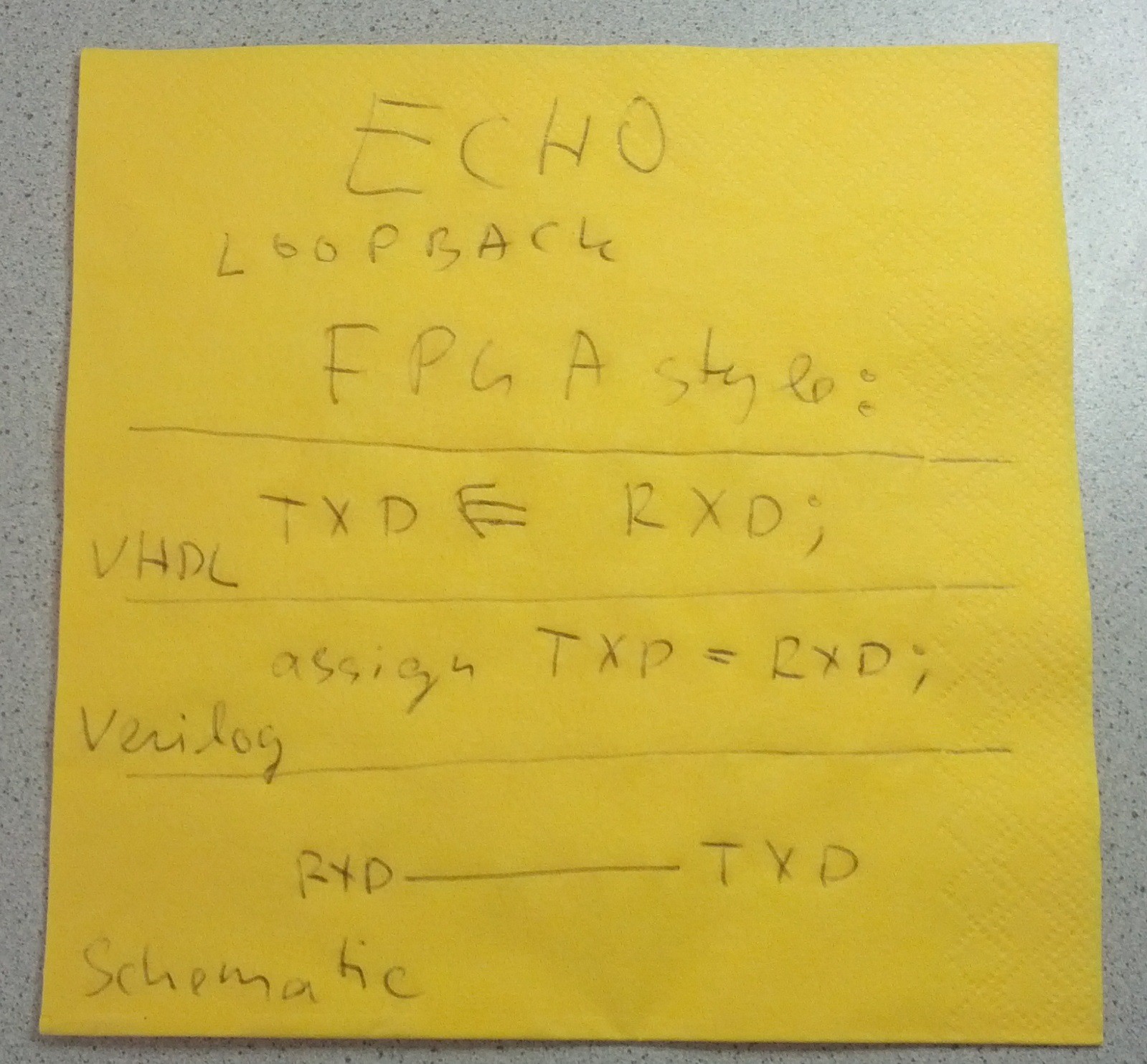
And this is how to test UART problem with FPGA - you create a HARD LOOPBACK without using the tweazers: you just say I want electrical signal from UART input to be forwarded to the UART output.
Whenever you have UART issue, be it with real RS232C cable or with FPGA, the first thing to try is echo.
If you get ECHO back then you know that
Echo loopback with Microcontroller is a bit harder task, it depends on the microcontroller, toolchain, language, peripherals, O/S and libraries being used. If the UART pins can be configured as GPIO, then the "hard loopback" can be implemented as tight loop with GPIO read and writes.
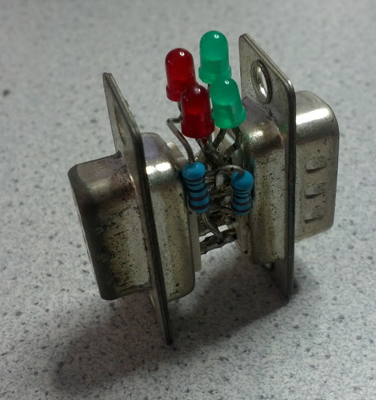
This is something I did maybe more than 20 years ago, and it is still around, it was even used recently to troubleshoot UART Cable on LPKF PCB mill.

Two DB9 connectors, 2 resistors and 4 LED's. All LEDs go to pin 5 (GND) resistors go to pins 2 and 3. Easy uh?
If you ever have the need to troubleshoot a RS232C connection.. and you have no tools, and have NOT made this one to help you, then I can not help either.
For me this simple tool has been valuable last xx years.
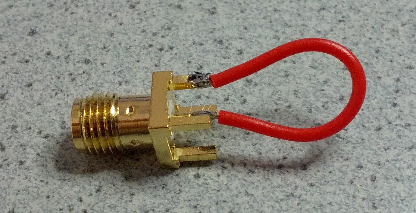
This device is always on my desk. Well usually, today I did not find it, so I had to hack a new one quick. Of course I always have a small bag of GOLD (those SMA things) close to me, so there was no need to stand up even.

Ready made pickup coil.
If you ever have to measure a Chrystal oscillator, then this is really your only option. With SignalHound spectrum analyzer, this pickup is good from so 10MHz, just hold it close the place the wire or pad is, and adjust the analyzer to the expected frequency - when doing wide sweep you may not see the spot. The first use of this coil, I did see 10.000.010 Hz, so 10 Hz offset. Of course if the signal can be picked up somewhere after the oscillator then that would also yield valid measurements, but when doing quick test, this is really easy way to verify clocks.
Create an account to leave a comment. Already have an account? Log In.
Become a member to follow this project and never miss any updates