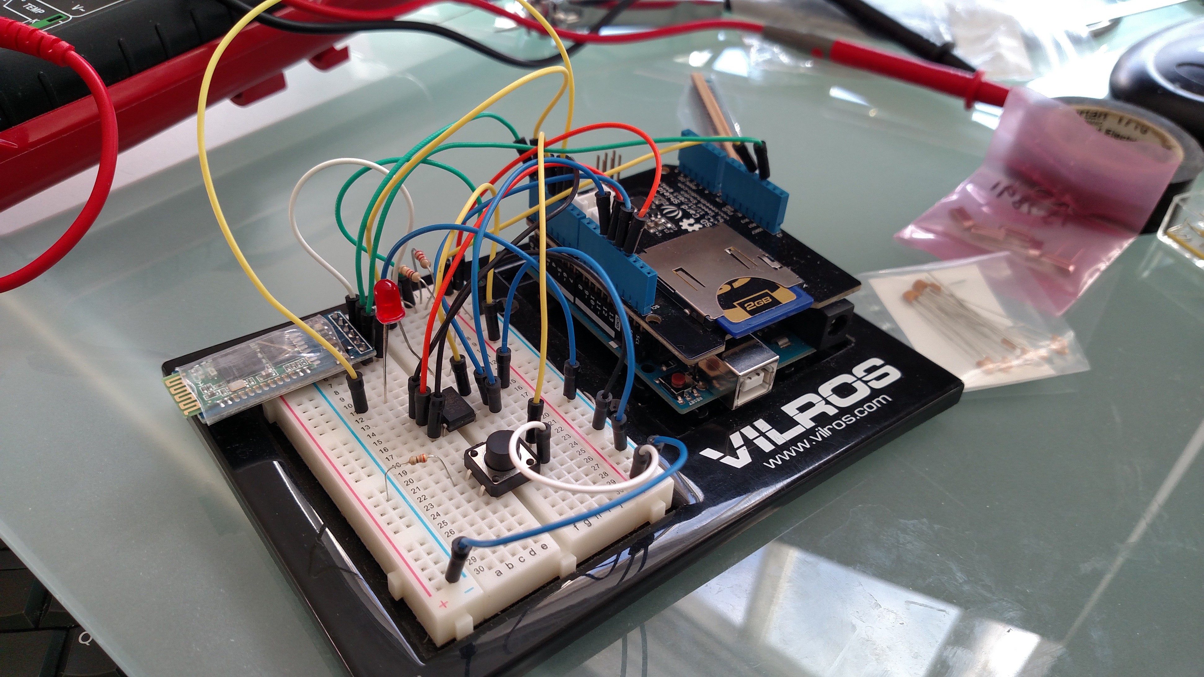
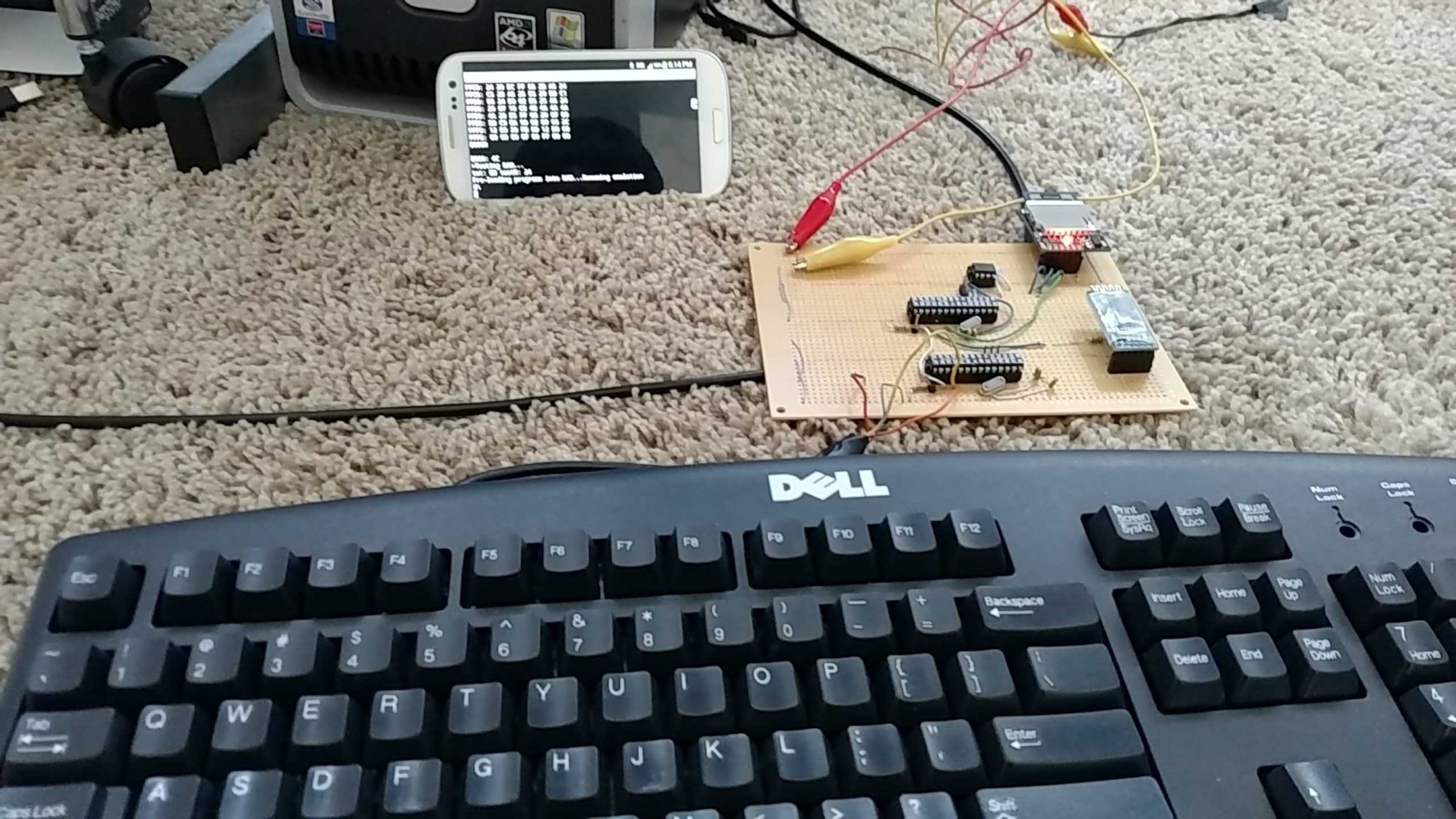
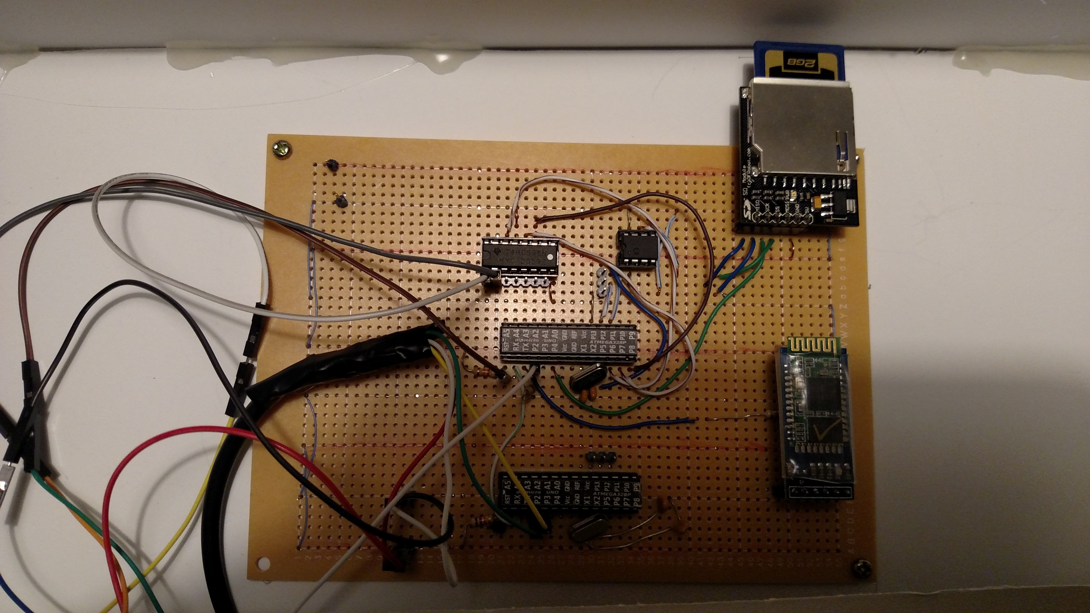
For this project, I have aimed to demonstrate not just what I have learned this semester, but attempt a challenge that would test much of what I’ve learned in my years at this university as well as my two-year internship. It has required both complex programming and detailed hardware design, and demonstrates countless concepts learned in my time as a Computer Science major and EET minor.
The project is an emulator of Apple’s original kit computer. The Apple 1 was a very simple hobbyist computer that was little more than an MOS6502 Microprocessor hooked up to a peripheral interface adapter that gave its programs input from an ASCII keyboard and could output to a character-based display. Some kits could also read from and write to a cassette deck, though I did not include this feature in my emulator.
The system’s BIOS, called the “Woz Monitor” by the community, only had a few simple functions. The user could type in a memory address in hexadecimal format, and the Monitor would display the value at that location. It could also display a range of locations, record keyboard input starting at a specified location, and run the program that started at a given location.
Simulation of this functionality was actually split between two Arduinos (which, in the final project, are just the bare ATMega328P MCU chips on a board, with clocks and pin headers to be programmed in-system by an Arduino running the ArduinoISP firmware). The first one interfaces with an old Dell PS/2 keyboard. It reads data in using the Arduino PS2Keyboard library, which converts the keyboard’s scan codes into ASCII values, and my program echoes those characters to serial output. The TX line is connected to the RX line of the main Arduino.
The main microcontroller serves several purposes. It runs the core 6502 emulation code, which is in the main “.ino” file. This file is nearly a thousand lines in length, and to keep my code organized, I had to split the rest into a few other files, using C+ classes. These other classes help it interface with the 64k RAM and SD card on the SPI bus, the shift register that displays the status lights, and the Bluetooth module used for the final output.

The main 6502 emulator code is fairly simple in theory, but large because of how much it has to do. The 6502 instruction set has nearly sixty instructions, and the emulator code has a C function for every one of them. It has many variables, representing the various registers, flags, and the program counter of the CPU. The actual main loop is fairly simple:
- Read in the byte from memory at the location pointed to by the program counter.
- Increment the program counter.
- Decode the byte read in as an instruction
- Execute the instruction.
Fetching the instruction and incrementing the counter are straightforward. Decoding and executing make up the majority of code. The instructions are just a single byte value, but there is a certain pattern to them. Instructions that involve additional reads or writes to memory have several different “address modes,” where the byte to be written to or read from could be at a location that is an absolute value specified by the next two bytes, a value relative to one of the CPU registers, or even a value stored at another location to be read in. I take advantage of the pattern that helps indicate this to avoid having to write a function for the nearly one hundred total unique opcodes.
All program instructions and data are stored in an external 64k static RAM module that uses the SPI bus. The 6502 CPU has a total 64k address space, but the ATMega328P only has 2k of program memory, which makes the external RAM necessary. There are four special memory locations (from D010 to D013) that control input and output that the Woz Monitor and other Apple 1 programs know to use. There are “readMemory” and “writeMemory” functions in the “MotherBoard” class I created that, when called, will check to see if the given memory location is one of these. If the location is one of the special ones, it will print a character to the console or read a character from the keyboard, otherwise it will go on to interface with the RAM using my “Memory” class the uses the SPI library.
Interacting with the RAM module is the biggest speed bottleneck of the project. Whether reading or writing, there is an 8-bit instruction that says what the SPI master is about to do, a sixteen-bit address to point to, and eight bits of data. This makes for a total of thirty-two bits that need to be shifted to read or write a single byte. The built-in SPI library can only do this as fast as two clock cycles per bit, and on top of that, the chip-select line needs to be pulled low and high before and after a read/write cycle. The real 6502 CPU could do this whole process in only a few clock cycles, since the entire data and address busses were parallel. Even though the Arduino’s clock is sixteen times as fast as the original Apple 1’s, the emulator is still slower overall.

The programs that can be run are stored on an SD card that is also on the SPI bus, and the functions to read from it are also in the MotherBoard class. It is accessed with Arduino’s SD library, and can only be read from in this application, though writing to it is possible with the library. When the Arduino is reset, the Setup function automatically loads in the Woz Monitor from the SD card into RAM starting at hex offset FF00, and the BASIC interpreter starting at E000 before the emulation code starts running.
To load other programs, there is a button on the case labeled “Menu.” The button is hooked up to digital pin 2 so that it can fire off an interrupt. The interrupt service routine sets a Boolean variable to “true,” signifying that access to the menu was requested. This variable is checked by the main loop so that it can be brought up in-between instruction executions. The menu allows access to the SD card in one of two ways:
If “1” is pressed, the user can enter a file name, and the contents of the file will be read in as if the user was typing them to the keyboard. These files have a text hex offset followed by text hex values. Since this takes a long time to run, I added a light that stays on until the user can use the keyboard again. If “2” is pressed, the user can give the name of a file, and a hex offset. The values of each byte in the file are then copied directly to RAM, starting at the given offset. Displaying the menu and getting user input are handled in the “Menu” class.
For the display, I’ve taken advantage of the fact that the real computer only had simple text output, and used a Bluetooth transceiver module to send text to a smartphone, running a free app called “BlueTerm,” that basically works like the Arduino’s serial monitor, PuTTY, or any other terminal app. The module was very simple to use, and other than having to divide the Arduino’s TX output down to 3.3v, I didn’t have to do anything special to make it work.
The case for the project has two buttons and two LEDs. One button fires off the menu interrupt, and the other shorts the Reset pin of the main MCU to ground. The two LEDs are status lights that are output from an eight-bit shift register. All eight bits can be written to in the project’s code, and I had originally intended to have eight status lights. Due to lack of time, I had to cut it down to just the Auto-Entry and Caps Lock lights, meaning it now takes three pins to run the two lights. The board itself still has pin headers soldered to the shift register for all of its bits, so more could be added with relative ease.
There were a few major challenges and hurtles with this project. Many of them had to do with using the PS/2 Keyboard. The reason that there is an extra Arduino involved in reading the scan codes is that the PS2Keyboard library did not seem to run well alongside all of my other code. Even though it uses interrupts triggered by the keyboard’s clock signal to know when to read the next bit of the scan code, it was almost as if it still had to be polled regularly for the characters to be interpreted correctly. When run as a part of the main code, character entry was very stuttery and often locked up or put in repeating characters.
Another challenge was the backspace key. For some reason, the Woz Monitor and other Apple 1 software use the ASCII code for underscore in place of the standard backspace code. This meant that in my code for reading the keyboard, I had to intercept the backspace and send an underscore. Additionally, since all the programs would output an underscore in place of a backspace, I had to intercept it when displaying it and send a real backspace. Finally, BlueTerm only moves the cursor back one location without erasing the character behind it when it receives a backspace, so I had to send a backspace, followed by a space character to erase the character on screen, followed by another backspace.
The final keyboard challenge was Caps Lock. All Woz Monitor and BASIC commands only work with capital letters, so having some kind of caps lock was a big help. Unfortunately, the PS2Keyboard library does not have a native support for caps lock, and even if it did, my caps lock status light was on the shift register controlled by the other microcontroller. To get it working, I had to go into the source code for the PS2Keyboard library, and add in a value to a table that it uses to look up the scan codes and get ASCII values. I chose to use the ASCII value for Tab, since it is not used by any Apple 1 software. This allows the main Arduino program to toggle its caps lock state when it sees this value come across on the serial line, and know to shift the value of letters coming in.
As mentioned, the core 6502 emulator code makes up the bulk of the project. Getting this to work was easily the biggest challenge. It was hard to figure out what was expected to happen when running 6502 assembly code that I did not write, and I had to gain a very good understanding of the Woz Monitor to get it working. To clean up the last few bugs, I eventually had to port the code to a C# project in Microsoft Visual Studio so it could be properly debugged with breakpoints and watches, rather than relying on serial printing statements from the Arduino. I found a simple “Test Suite” program online to help me out, that is fairly short, but calls all of the 6502 instructions at least once, and puts the processor in a state where you can tell what test failed.

I am more or less pleased with the way this project turned out. Work on it began shortly after the beginning of the semester, anticipating having a bigger final project. Were it not for having to shoehorn the shift register and interrupt into my design to meet the requirements, and having an additional project assigned, it probably could have had a few more features.
I would have liked to do real video output to a VGA monitor, but the Arduino simply isn’t fast enough to produce such signal timing, and hardware solutions to help with it are expensive and limited. There is an “ArduinoTVOut” library that can generate a composite video signal, but its maximum resolution is still too small to produce the forty character column width required. I probably should have also used a smaller keyboard. The one I chose has many keys that do absolutely nothing, but PS/2 Keyboards are hard to come by these days, and I had the one I used laying around collecting dust.
 Alex Bowen