I've taken a break from CP/M Plus for the time being so I don't lose interest in the project. I'm currently looking at implementing a colour graphics overlay board. Presently, the colour is generated by an ATmega164P, a 74HC74 flip flop and a 74HC08 quad AND gate. I'm using another ATmega for the time being to make sure the theory works in practice. The ATmega is clocked with a 17.7MHz crystal. This is a standard frequency that is exactly 4 times the frequency of the PAL subcarrier (4433618.75Hz - notice how the frequency is accurate to a quarter of a Hertz).
The 74HC74 is configured to give four 4.43MHz outputs from the 17.7MHz clock, one each at 0

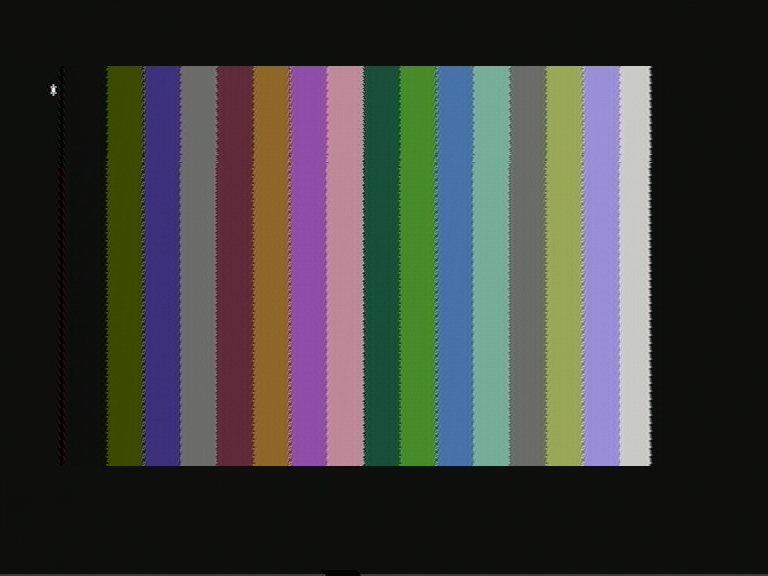
This is a capture of the colours the PAL generator can produce. The dot crawl is made worse by the ATmega's interrupt jitter, which can't be removed because I'm using a hardware interrupt pin to synchronise to. Not a timer. I won't be using an ATmega in the final version, so the jitter will go with it.
The asterisk in the corner is the prompt for the ROM monitor. The 80 column text is mixed resistively with the colour background, and because the dot clock for the text is completely different to the colour carrier (13.5MHz compared to 4.43MHz) there is virtually no colour generated around the characters. The text is a little brighter than the colours and is quite visible. This is why the main ATmega is clocked at 27MHz. It is an exact multiple of the NTSC and PAL line frequencies. To add colour, I just need to mix the colour frequency with the existing signal. I'll make an NTSC implementation later, which shouldn't be difficult (he says...).
PAL's fix to this problem is to invert the phase of one of the colour components present in the signal every other line, hence the name "Phase Alternating Line". The previous line is stored in a delay line and is combined with the present line. If there are phase errors between lines, they cancel themselves, which results in reduced saturation. This is much less noticeable than the colour changing.
This extra complication needs to be taken into account when designing a PAL encoder. At first when I got colour on the screen it was running in "NTSC4" mode, which is used on some DVD players. This is somewhere between PAL, where the colour frequency is 4.43MHz, and NTSC, where there is no phase swapping between lines. The colours would appear on my newish television which supported the standard, but not on my Commodore monitor which only supports regular PAL.
The ATmega has four bits on a port which controls which colour frequencies are enabled. There is also a register which stores the current number to send to the port for the colour burst frequency. This register has the two bits which control the red component inverted every line, using the XOR function. This introduces the 180
However, there was only blue and yellow. These are the colours generated by the blue component of the signal. The problem was I needed to invert the red component every line as well. If it isn't inverted, the same phase of the red signal between lines gets cancelled by the delay line. That is, the saturation is reduced, to the point where there isn't any. It's not as simple as XORing the numbers being sent to the port. What needs to happen is the two bits which control the red component's output need to be swapped.
I solved this with two lookup tables, for now. The pointer alternates between the two tables every other line. When I make a 'real' hardware implementation it'll be easier to do with discrete logic.
I'm aiming to have a 320x200 pixel display with sixteen colours per pixel. This will require 32kB of static memory. The Z80SBC can address 256kB in total with bank switching, so the extra video memory can be switched in to be written to.
Update: I have made a short video of the board in action.
 256byteram
Discussions
Become a Hackaday.io Member
Create an account to leave a comment. Already have an account? Log In.