 Jaspreet Singh
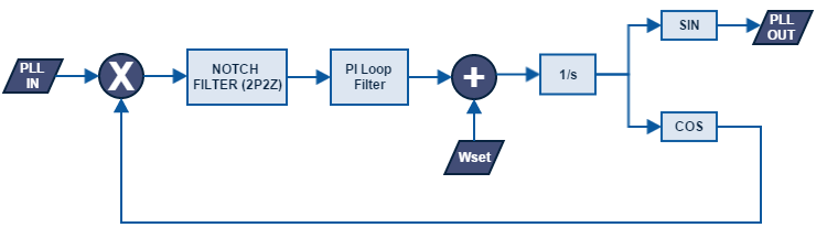
CONTROL DESCRIPTION:
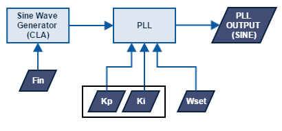
Consider the control diagram as shown above.
PLL generates two signals, One Sine and second Cosine. The cosine signal is feed back and multiplied with PLL input signal.
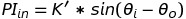
Let PLL input be

Let the cosine output of PLL be

The input to the Notch filter,

Where wi = Frequency of PLL input signal, wo = PLL set Frequency (at steady state) and K = Magnitude of PLL input signal
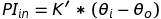
Using trigonometry, we get

If wi = 50Hz (Ideal grid freq. in India) & wo = 50Hz (at steady state), We have a twice frequency component (wi+wo) in the above equation. To remove this, the Notch filter is tuned at 100Hz. The input to PI thus becomes,

NOTCH FILTER DESIGN:
A Biquad Notch filter will suffice for our application.
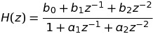
The Direct Form II equation for a biquad filter is given as,

where x(n) = Present Input and y(n) = Present Output
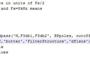
The numerator and denominator coefficients can be computed using the excel sheet given below (in "files" section of this page).
PI LOOP FILTER DESIGN:
One way to design a PI is using the so called Velocity Algorithm,

We only need to store present and previous sample values.
SINE/COSINE GENERATION:
We can generate sine/cosine using integration as explained in [1].


The EQUATIONS for SINE/COSINE generation:
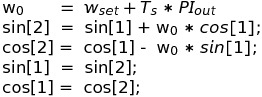 where Ts = Sampling Frequency, Wset = PLL set frequency
PLL TESTING:
For testing the PLL, i created a Variable Frequency Sine wave generator using CLA (Control law accelerator) of the Delfino Microcontroller. This generator runs in backend and can be used generate Sine wave input for PLL testing.
Watch the PLL in action in the video below:
 Bruce Land
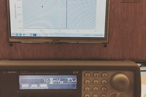
 Dan Kisling
 NotBlackMagic
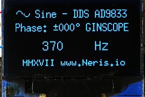
 Gintaras Valatka