I started out just making a Sequential Shift Light for my 2008 WRX and found this project.
As I started looking into my car I found there was no good way to pull the RPM signal from the ECU using traditional PPR from the ECU I had to switch gears and use the CAN bus. Here is my version on the breadboard.
After bread boarding and testing upon testing I came up with a good design and code. I got rid if the menu system, 7 seg display and encoder once I had fine tuned the brightness and shift points I liked and just hard coded them. That lead me to this first hardware version
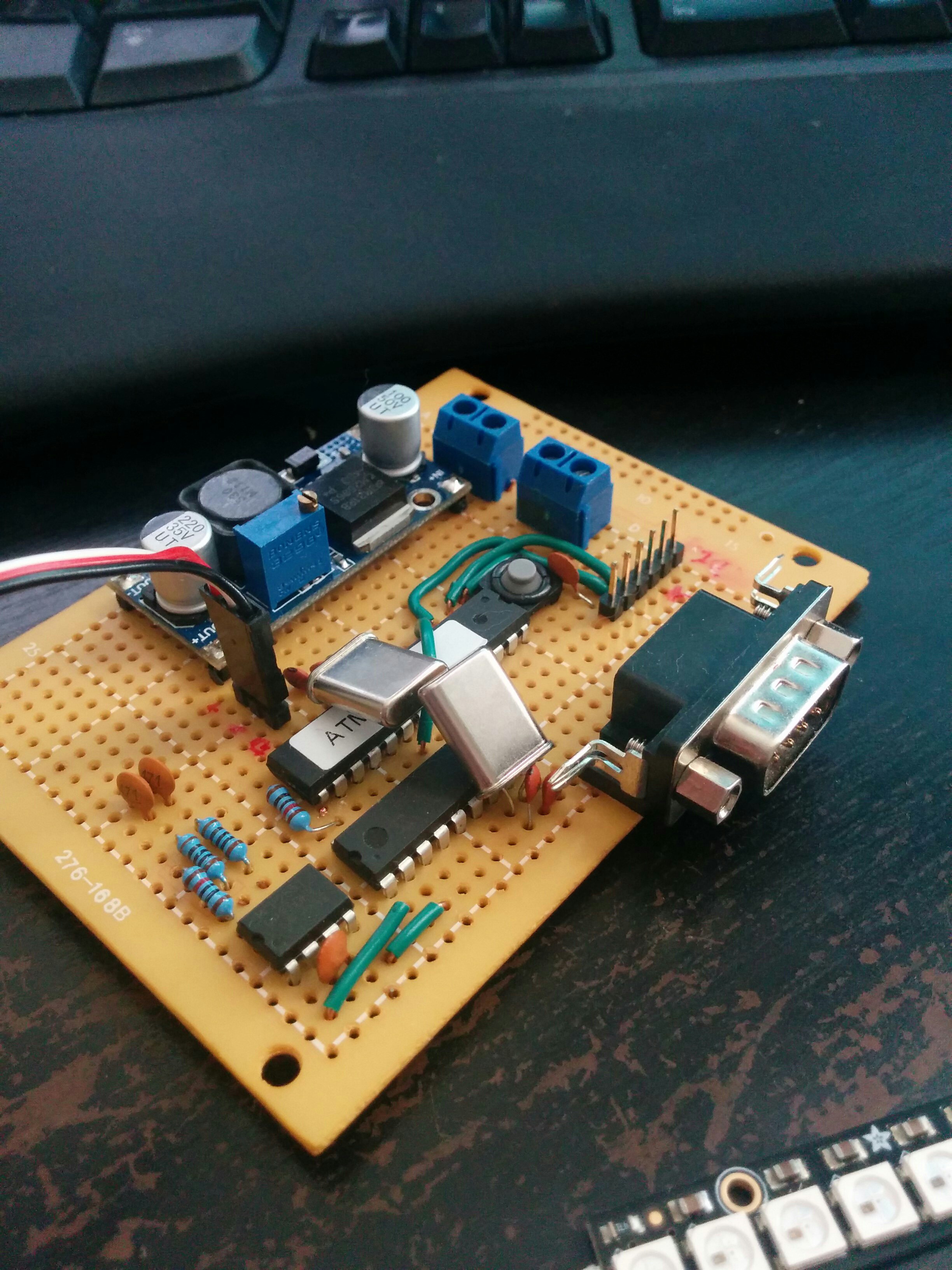
I drove around with this in the car for a little while. It was a bit big and didn't really fit anywhere under my dash so it was visible. In an effort slim it down and make it a bit more robust I had a board made up from OSHPark.com
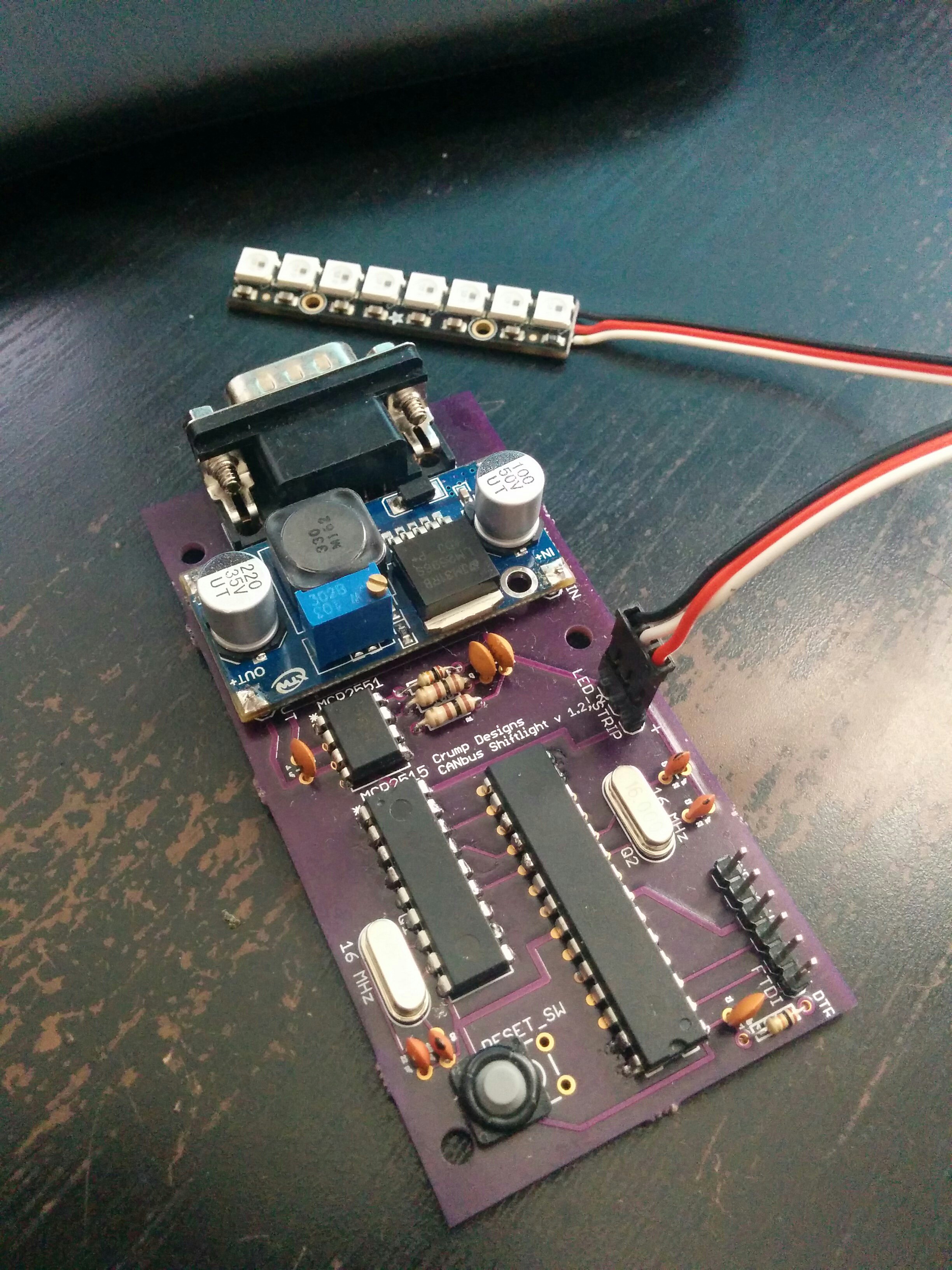
I'm still using this in my car today and works fine for a shift light, I've also tried using it as a boast gauge, engine temp, intake temp etc. The more I experimented the more I realized I needed to have access to all the arduino's pins. I started out with just a prototyping shield with the MCP2515 and MCP2155 on top of an Uno. Then added GPS to start doing data logging of location and engine stats. but who wants to look at a big table of numbers. So I added a TFT display. that caused me to move to a Mega 2560. Now I have it displaying all the engine data, calculating MPG instant, trip, and for the last 5 and 30 minute intervals. Using the GPS to compare trip distance and speed also displaying location, altitude, and time.
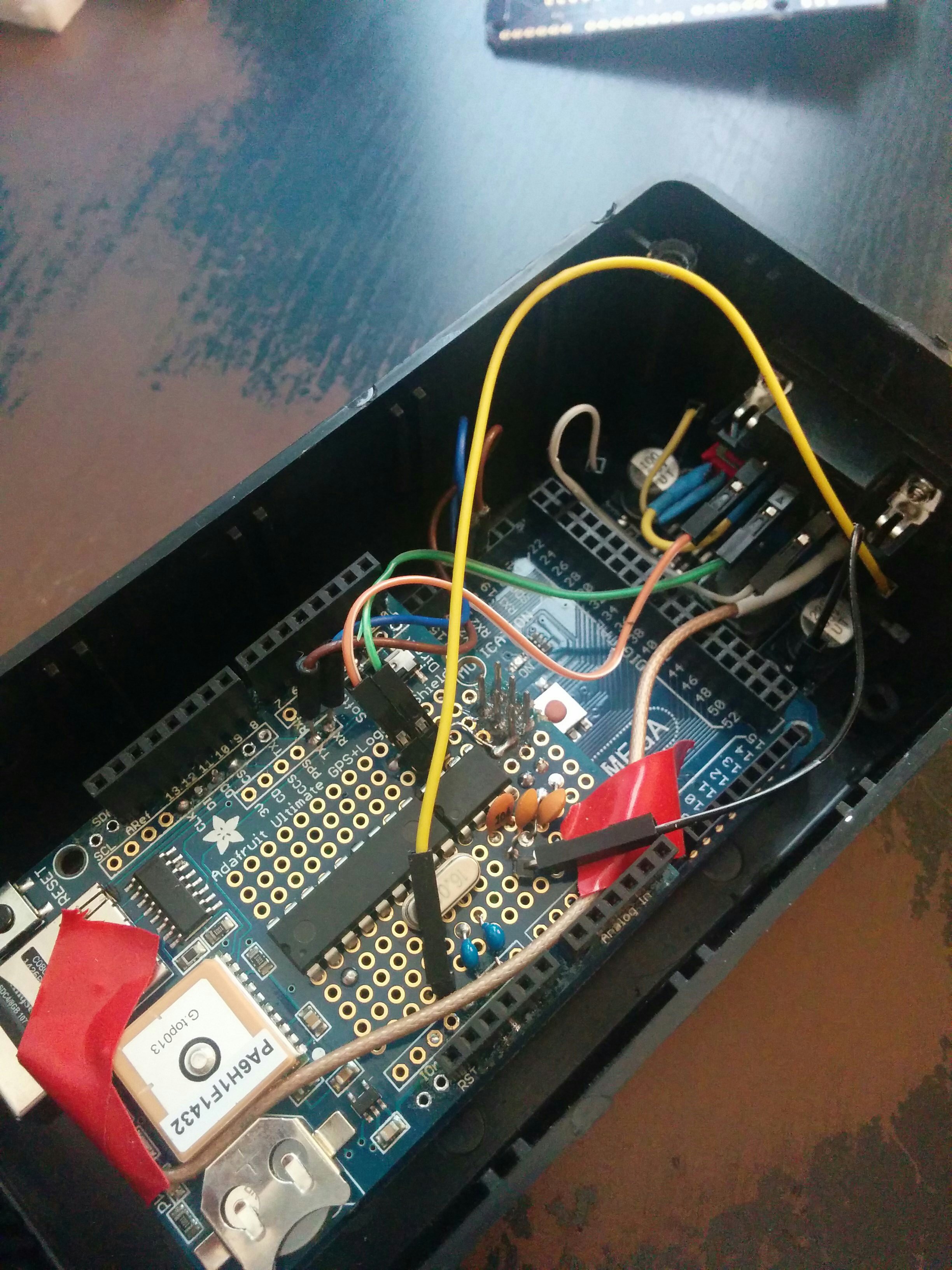
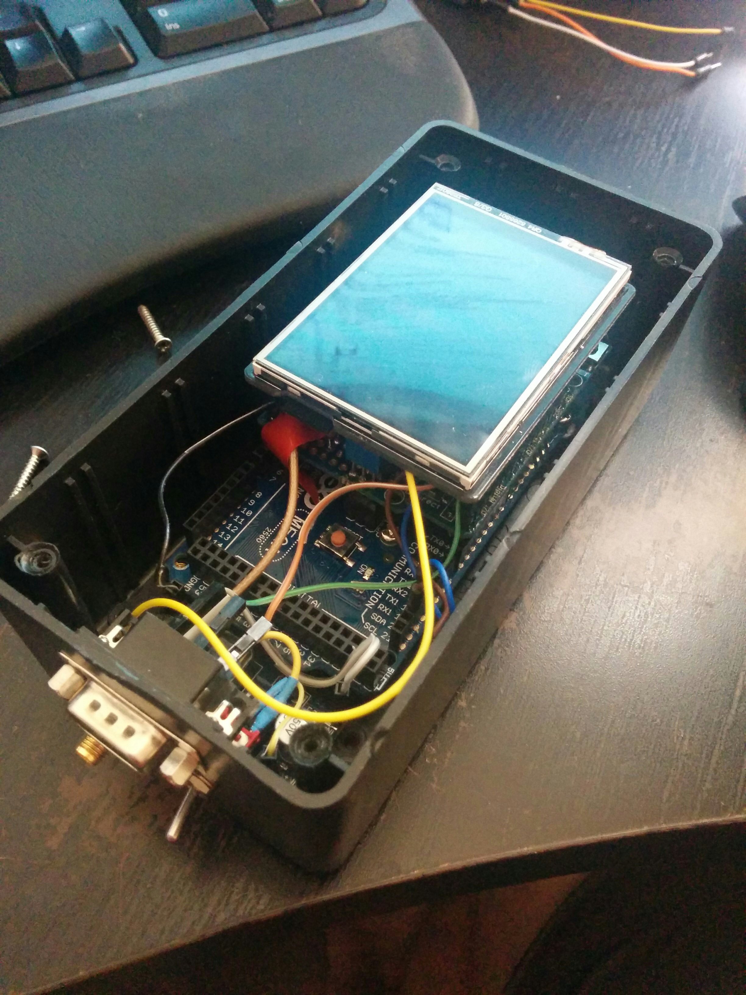
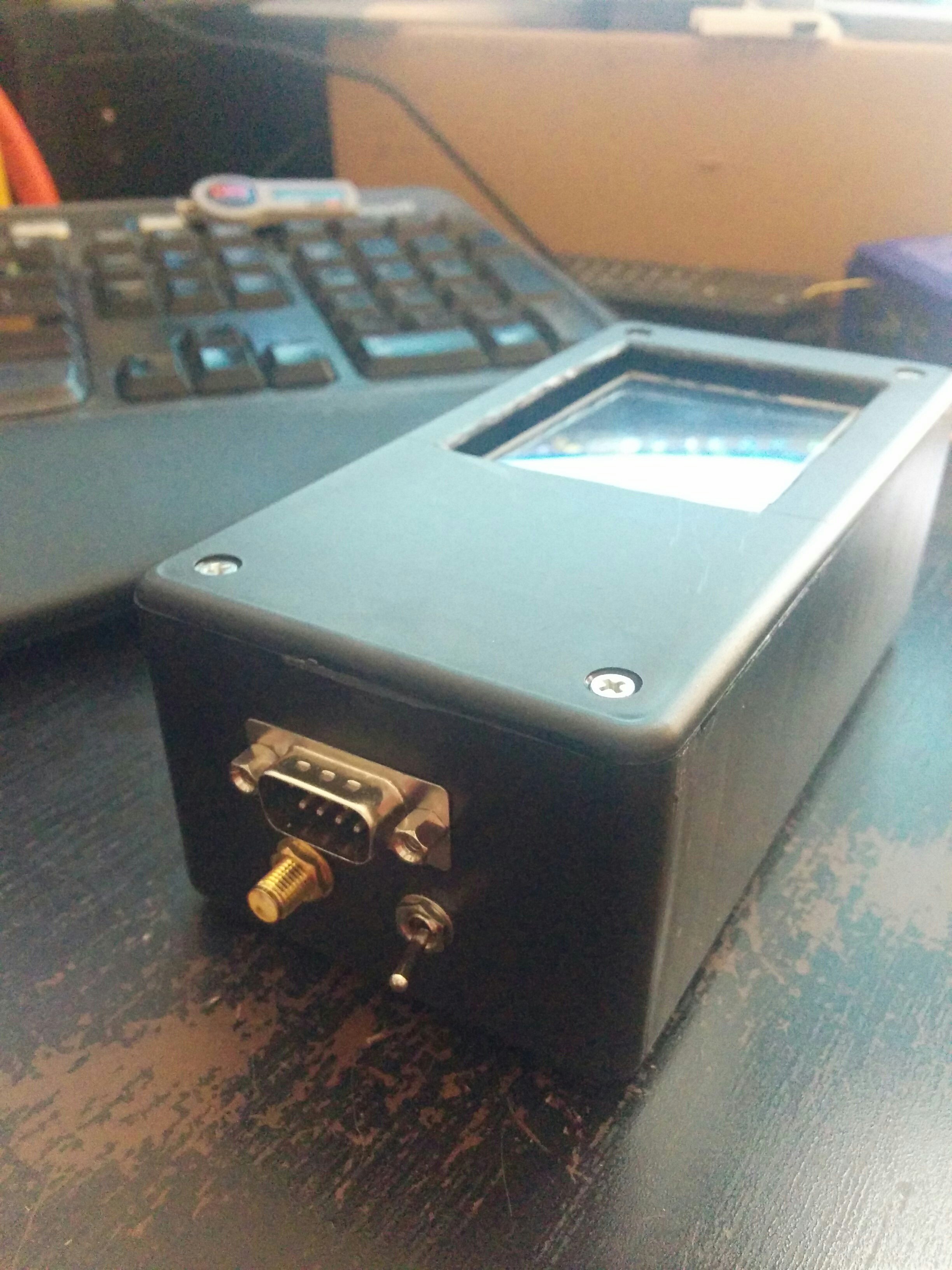
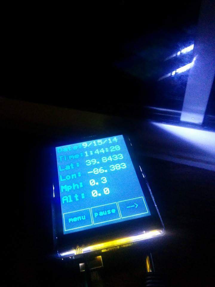
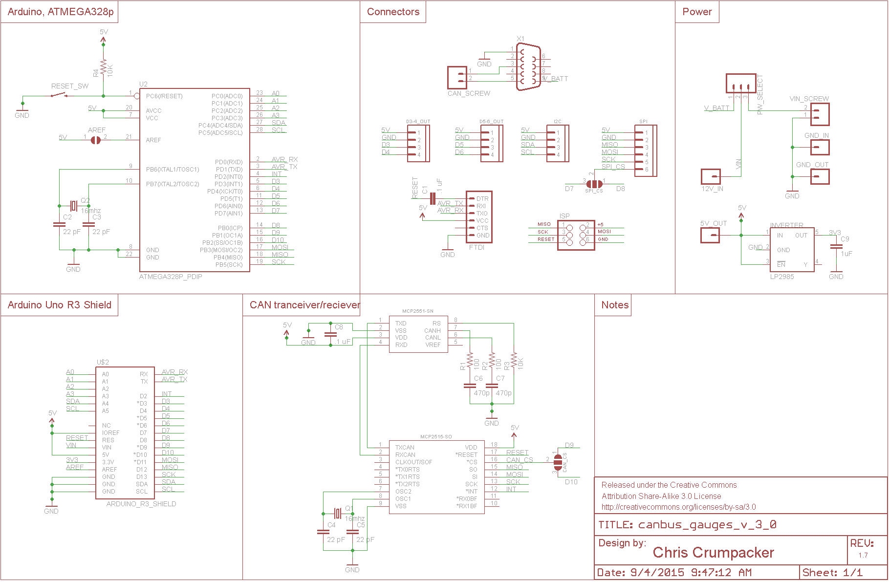
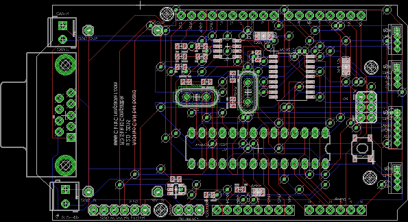
Now it's back to being huge and unsightly but it works well. I know that I can cut back on the TFT display and move to something a bit more light weight like a 2-4inch i2c OLED display and get it all running on a standard arduino 328p. I've been designing a new board and have the first run already made but there are some issues with it that will require a new set. Also I'm waiting on ordering all the surface mount parts till I finalize the new board design. Currently this board has the DB9 for connection to the ODB-II port to pick up the CAN bus and power. It will have an onboard 5v step down regulator that can handle the crazy spikes in voltage you see in the automotive power. past that it is a standard Uno R3 pin layout around the 328p and CAN chips. It will have an FTDI interface and also some JST connectors tied to different io ports.
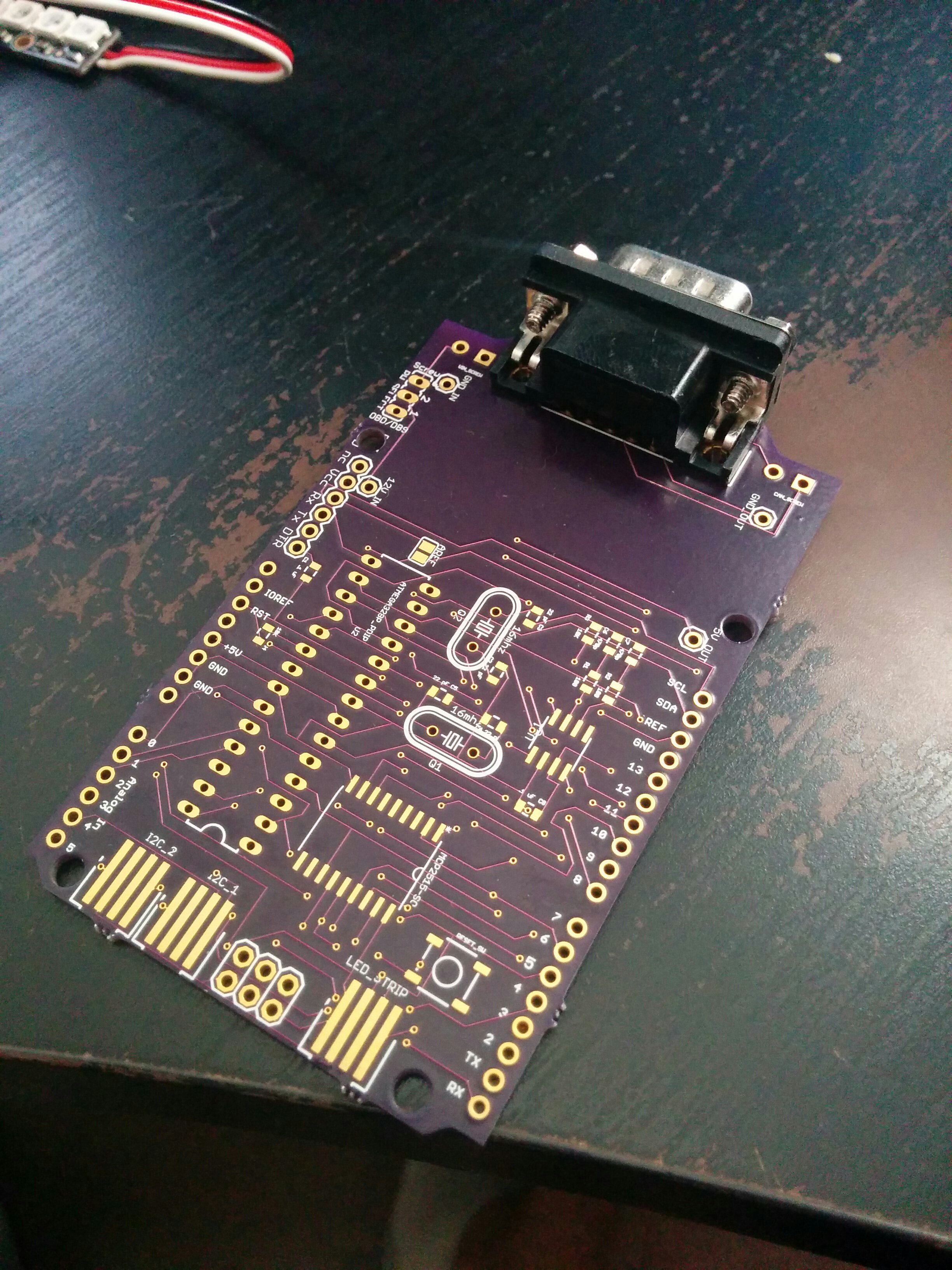
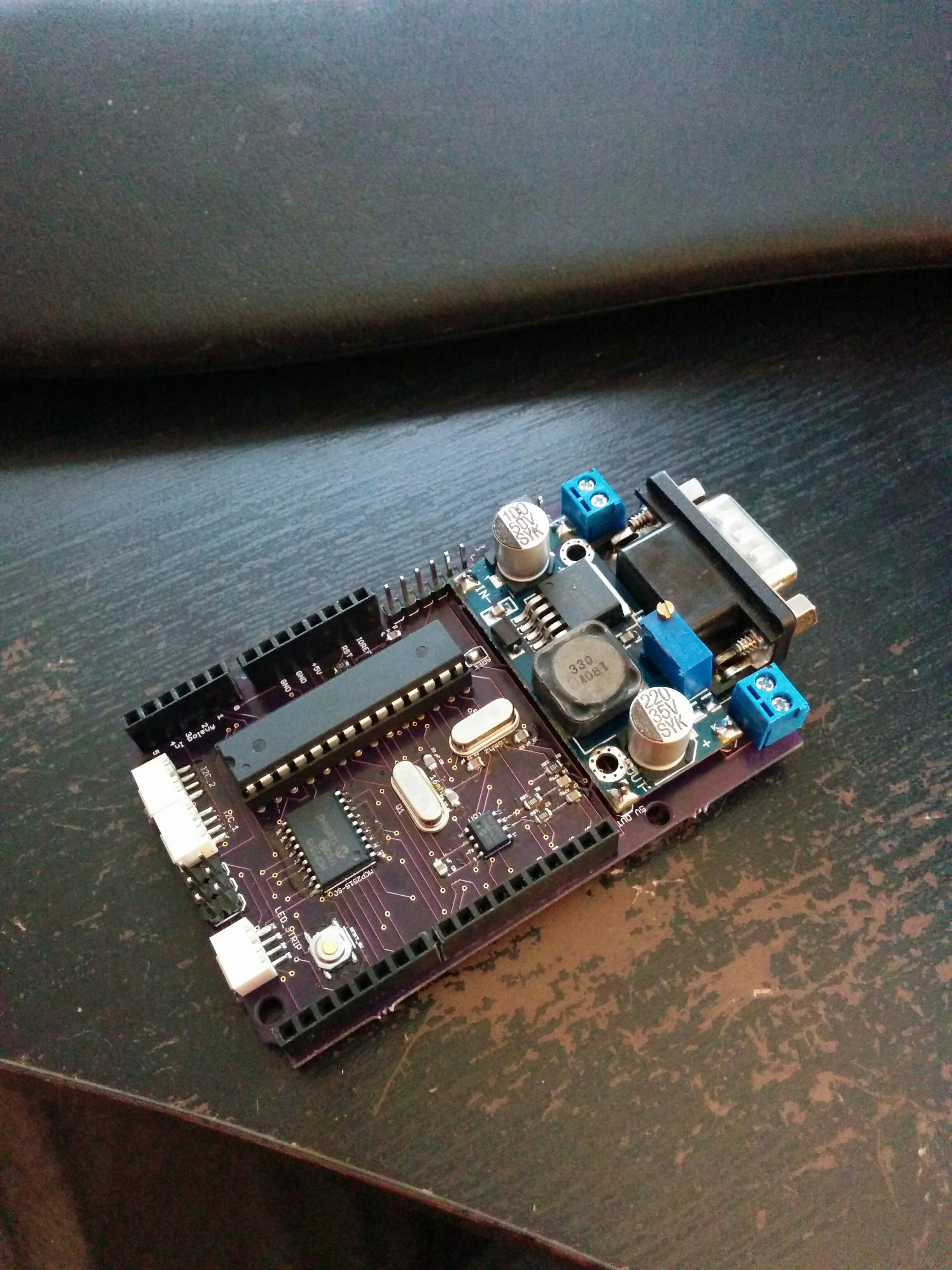
Once the version 3 boards arive I'll populate them and update
 Chris
Chris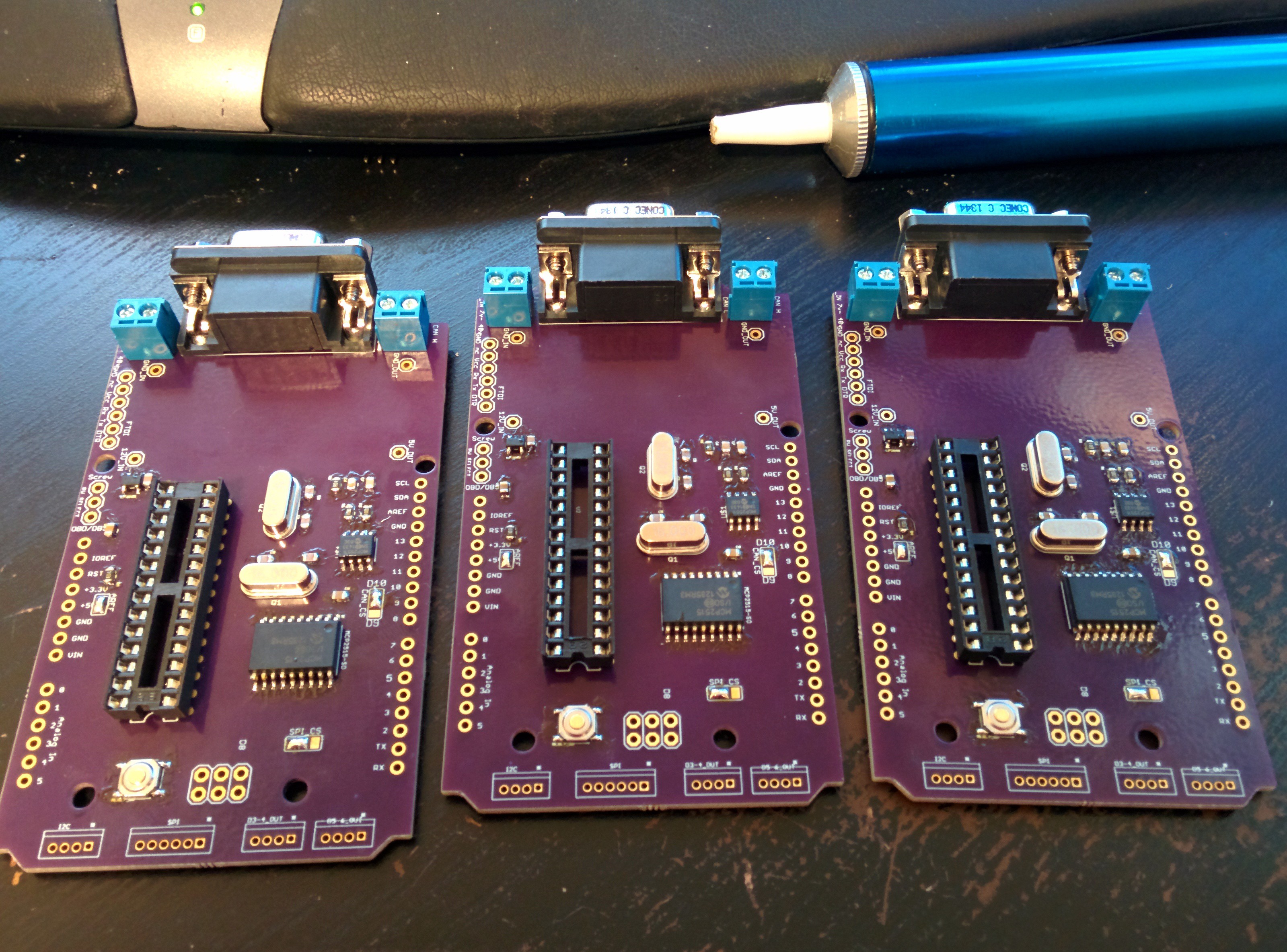


Found your project by searching here. I'm doing something a bit similar. Check out:
https://hackaday.io/project/19796-omzlo-one-the-connected-arduino-compatible-board