 Antti Lukats
This is how PINAPI can be used together with microfpga concept and simple ASIO (A Simple I/O).
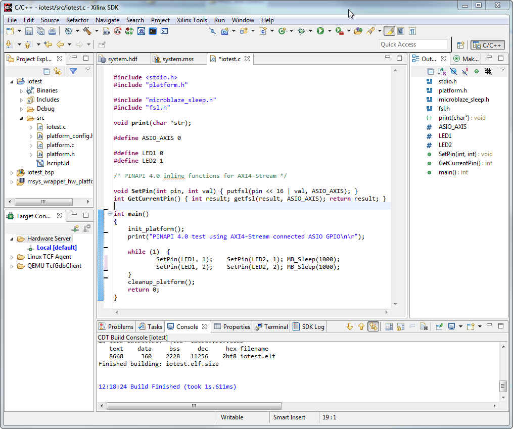
This is the software view, for simplicity PINAPI functions are declared as in the main.c. What this code does? Well it does blink a LED, or to be precise two LED's on this board:
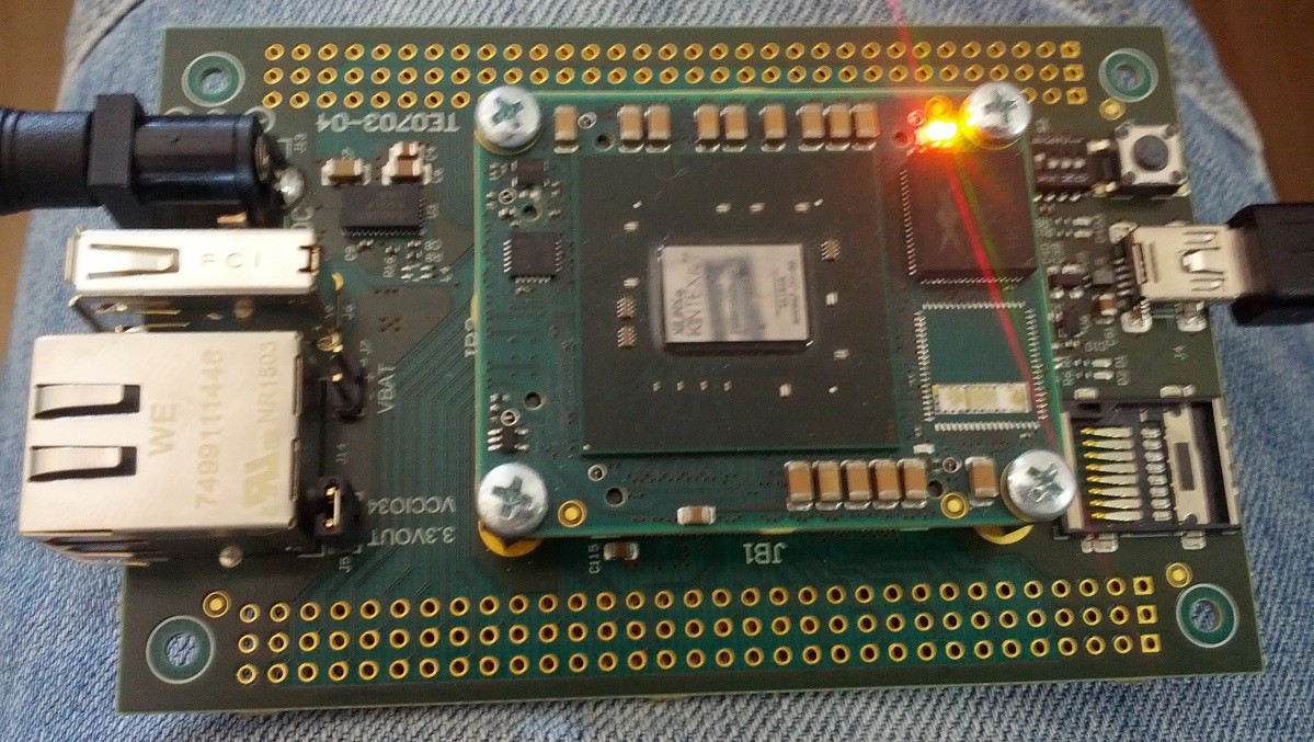
This code worked first time compiled and downloaded to the FPGA.
Wait a moment but there is no Processor? To where did the code go then?
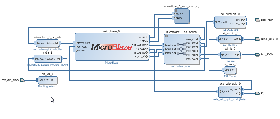
Here is our Processor, it is FREE for everyone no license fees. Mouse configurable. Everything here is done by a few mouse-clicks. All input output pins are magically connected to correct physical pins of the hardware.
P0 is generic ASIO GPIO connected to all I/O pins making them all equal. In this case this single GPIO port has 152 pins. This FPGA design was "clicked together" and it worked first time tried, no debugging or troubleshooting involved.
Why? This use case is "in system testing" - a programmable device is converted from "nothing" to Microcontroller (yes look at MicroFPGA.COM ... soon).
This Microcontroller can access pin_map file generated from PCB design and used by the Vivado Board Awareness (this is the magic that connects the I/O s to where the belong).
This Microcontroller can test the inputs outputs using local loopback, check for open and shorts, and report go no-go on LEDs and detailed test report on UART.
All it takes are some mouseclicks, and few lines of code for the PINAPI
Discussions
Become a Hackaday.io Member
Create an account to leave a comment. Already have an account? Log In.