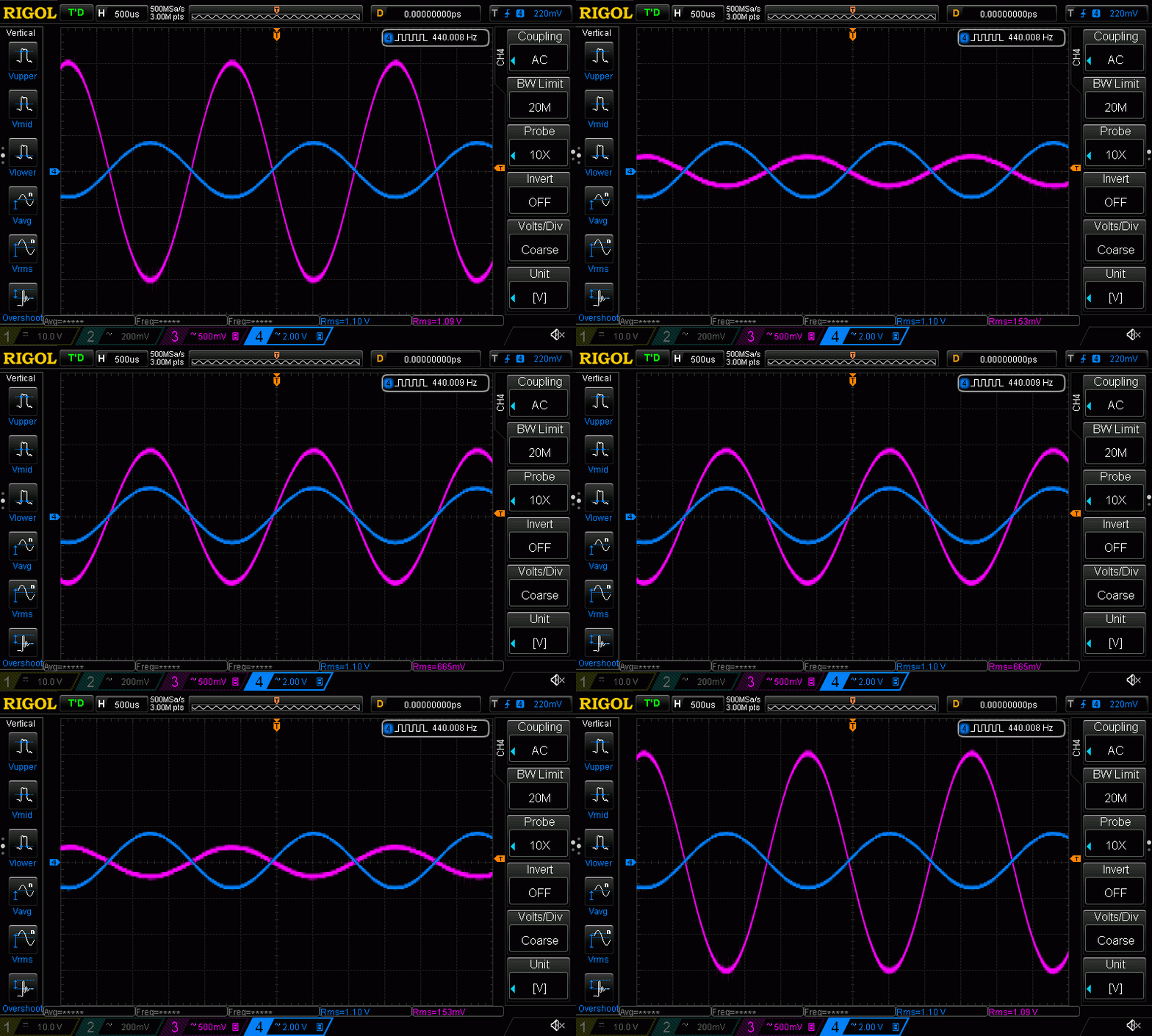
In the animated image, the blue sinus represent an analog input signal of 440 Hz, and the magenta moving sinus represent the multiplied output of the circuit. The digital multiplication factor is dictated by the Arduino program, and it varies in time from -1 to +1. Because the multiplication factor varies, the magenta output also varies, and that is how the animated picture was produced.
 RoGeorge
Discussions
Become a Hackaday.io Member
Create an account to leave a comment. Already have an account? Log In.