-
Code Overview 5: Project Structure
04/03/2018 at 03:53 • 0 commentsHexabitz software is released as a compiled HEX file and a uVision project along with source files for each module. The project folder contains the following subfolders:
- BOS: Contains source files for the BOS.
- H01R00 (or other PN): Contains source files for this module.
- MDK-ARM: Contains uVision project files as well as output files (assembler output, linker output, compiler output, etc.)
- Thirdparty: Contains source files for other libraries used in the project (e.g., HAL, FreeRTOS, etc.)
- User: Contains user-modified files used for this particular array/project. This folder includes main.c that contains the FrontEnd Task, the topology header files and the project header file project.h.
Updating to Latest Release
It is always recommended to update your projects to latest software release to get new features and bug fixes. Check release notes here for details on each release. To update your project to latest release, simply keep the user folder and replace all other folders with those in the release Dropbox. To maintain this level of portability, you should try to keep all your custom code in main.c and project.h files.
-
Using the Command Line Interface (CLI)
04/03/2018 at 03:46 • 0 commentsConnection
Use your favorite serial terminal emulator tool to access the serial COM port of your computer and thus Hexabitz CLI via a USB-to-UART cable. Some examples include RealTerm, Putty, HyperTerminal and SecureCRT. The configurations displayed here are for RealTerm but they are similar to those in other terminal emulators.
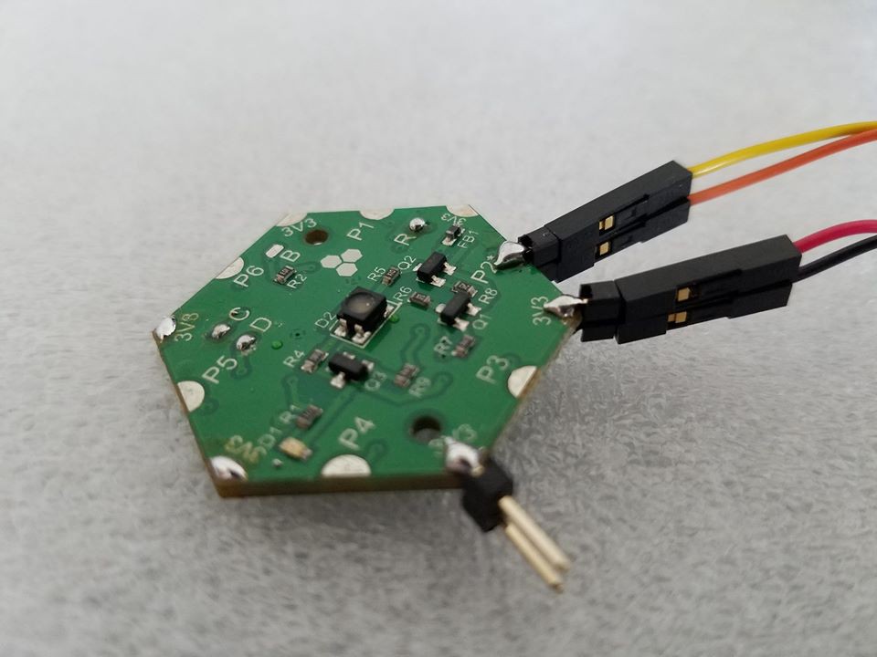
If you use standard FTDI USB-UART 3.3V cable for power and communication, connect the colored cable wires as follows:- Red to 3.3V (top power pad, i.e., corner edge pad).
- Black to GND (bottom power pad, i.e., corner edge pad).
- Yellow to TXD (top communication pad, i.e., side edge pad).
- Orange to RXD (bottom communication pad, i.e., side edge pad).
![]()
RealTerm Configurations
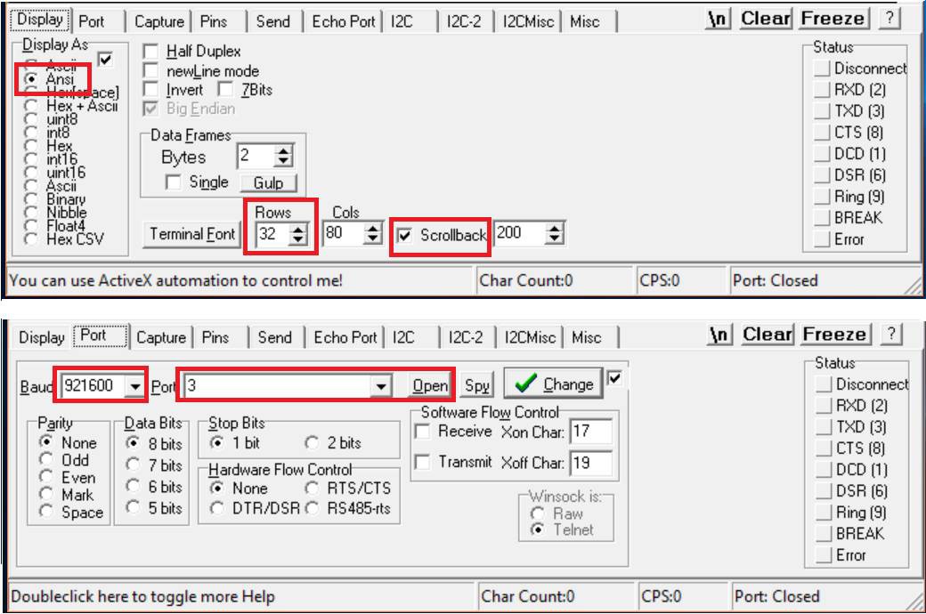
In RealTerm Display tab, select Ansi as data display mode. This mode allows you to use the BACKSPACE key to delete previous characters. Optionally, enable Scrollback and increase number of Rows to a suitable number (e.g., 32).
In the Port tab, select 921600 baudrate and open the appropriate COM port. The port will only show up after you power the module and usually it will have \VCP (virtual COM port) in its name.![]()
Once you open the port, press the ENTER keyboard key to start the communication session. You should see the CLI welcome message shown below. It tells you the ID of the module you are connected to and through which array port. Note if the module is native, i.e., not part of an array via a fixed or explored topology, it will show up as ID = 0 (unless you change default ID in the code).
![]()
Setting up Baudrate
Default baudrate for all array ports is 921600. You can change this rate with the following methods:
- Connect P1 TXD and RXD together momentarily while power-cycling the module. This will setup all array ports to 115200. Once you connect to a CLI port, other messaging ports restore their default baudrate. Note that the CLI will restore its default baudrate on the next power cycle.
- Change the value of BOS.clibaudrate parameter in the CLI using set Command. This will save the value to the emulated EEPROM so that you can use the new baudrate each time. You need to reset the module to apply the new baudrate. Note that similar to method 1, the new baudrate will apply to all ports until you connect to the CLI.
- Change the value of BOS.clibaudrate parameter in the code and call this API UpdateBaudrate(port, baudrate) to apply the new baudrate to a given port. You can also save it to EEPROM using this code (It will be loaded automatically from EEPROM on each startup):
EE_WriteVariable(VirtAddVarTab[_EE_CLIBaud], (uint16_t)BOS.clibaudrate);
EE_WriteVariable(VirtAddVarTab[_EE_CLIBaud+1], (uint16_t)(BOS.clibaudrate>>16));
If you want to restore the default CLI baudrate, you can either:
- Set BOS.clibaudrate to default value either in CLI or in code as shown above.
- Initiate a Factory Reset by connecting P1 TXD to programming port RXD or to last port RXD while power-cycling the module.
- Set all parameters back to default using default params Command or the following code:
memcpy(&BOS, &BOS_default, sizeof(BOS_default));
SaveEEparams();
General Usage Tips
- Type help anytime to view the list of Commands enabled in this module (and this firmware). You can figure out the firmware version and compile time and date using the status Command.
- If you misspell a Command you can use the BACKSPACE keyboard key to delete last characters and replace them with correct ones as long as you have not pressed ENTER yet. BACKSPACE does not actually work in the terminal window as in a text editor but it will still work fine with the CLI. You cannot clear a character from the terminal window for example. When you press BACKSPACE, the blinking cursor will move back one step but the previous character will stay displayed. It will be removed, however, from CLI buffer. If you write a new character, it will replace the old one on the terminal window and it will be added to the CLI buffer.
- If you misspell a Command and press ENTER, it will be ignored and you will get an error message Command not recognized. This will happen, as well, if you type in the Command with fewer parameters than expected. If you type more than the required parameters, then extra parameters will be ignored. Command parameters are separated by at least one whitespace (SPACE key) and they will be parsed according to their order.
- If you type in multiple whitespaces between parameters they will be parsed correctly. However, maximum number of characters in each command should not exceed 49 (it’s adjustable in the code).
- If you hit ENTER without writing anything, the last Command will be repeated.
- All CLI commands and parameters are case insensitive. You can write in lower-case, upper-case or mixed-case and they will recognized.
- Each module is referred to by its ID prefixed with # (e.g. #7) or by its alias name.
- The general format for a Command is:
module.Command parameter1 parameter2 parameter3
where module is module ID or name. Some examples:
#2.ping
#0.on 100
alpha.ping
North12.off
- If you are typing local Commands, i.e., BOS and module Commands to be executed locally, you can remove the module. prefix and type in the Command directly, or replace module ID/name with the keyword me:
me.ping
ping
- If you are broadcasting a command, replace module ID/name with the keyword all:
all.ping
- Module ID cannot be modified in the CLI. It is hardcoded inside the code through preprocessor directives. When exploring an array, all native modules will be assigned sequential IDs according to their distance to the module where the exploration was initiated (this module will get ID 1). Module alias name can be used anywhere a module ID is used. If you rename a module again the new name replaces the old one. Once you rename a module, its alias name will show up between parenthesis when you ping it:
>name john
Module 0 is named john

[Press ENTER to execute the previous command again]
>name bob
Module 0 is named bob

[Press ENTER to execute the previous command again]
>bob.ping
Hi from module 0 (bob)

[Press ENTER to execute the previous command again]
>ping
Hi from module 0 (bob)

[Press ENTER to execute the previous command again]
- Module alias name is stored in emulated EEPROM and loaded back on each power cycle. It’s not shared, however, with other modules in the array.
-
How to update module firmware
04/03/2018 at 03:39 • 0 commentsThere are currently two ways to load and update firmware on modules. Both ways work on individual modules only. You cannot yet do mass update for the entire array.
1. Using ST Factory Bootloader and Array Ports
The microcontroller (MCU) used in Hexabitz mainstream implementation comes from the manufacturer (ST) pre-loaded with a small application called factory bootloader. This application allows loading a new firmware to the MCU via one of the UART interfaces connected to array ports. The port that enables bootloader-based update is marked with (*) . For this process, all you need is a UART-USB converter cable and a special application from ST called Flash Loader Demonstrator.
In general, when the module is virgin, i.e., it has no firmware at all, it boots automatically in factory bootloader mode and you can upload firmware right away. However, when the module is already running a firmware, you need to force it to boot into the factory bootloader. You can do that with either one of these two methods:- Using the update CLI Command. Once you execute this command, the MCU will leave the running application and jump to factory bootloader. If you are already connected to the programming port, you will need to close this port in RealTerm (or any other terminal emulator) before you can use it to connect to factory bootloader.
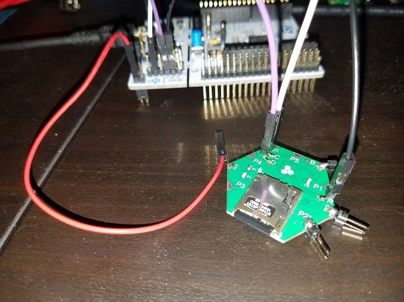
- Applying 3.3V on module B (Boot) pad while power cycling. Easiest way to achieve this is to connect a female-to-male jumper wire to one of power ports (edge ports) top connector, and then touch the B pad while power cycling the MCU.
![]()
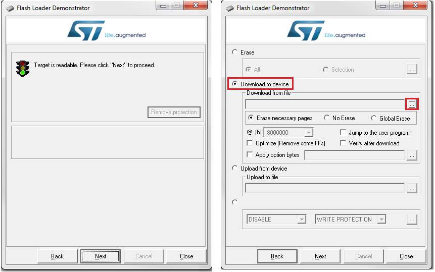
Once the MCU is in factory bootloader mode, connect the USB-UART TXD/RXD (yellow/orange) wires to the appropriate port and run the Flash Loader Demonstrator. Select the appropriate COM port and leave other connection settings to default then click next. If everything is working correctly, you will see a green traffic light with “Target is Readable” message. Other wise, if the module did not boot in bootloader mode correctly, you will get a red traffic light. Just power cycle and repeat the process again. Click next to select the default MCU Flash algorithm and another click to reach the programming tab. Choose “Download to Device” option and select the module firmware (it should be a HEX file). You can specify a full memory erase or only necessary pages. You can also enable verification. The “Jump to user program” option automatically runs the application after it has been downloaded. Otherwise, you will have to power cycle to run the application.
This article explains how to perform remote bootloader update, i.e., updating a module while connecting to another module.
Note 1: If you are not powering the module from the same USB-UART cable (or another cable connected to your PC), then you need to connect module GND and the PC GND together. Just connect the GND wire on the USB-UART cable to a module GND pad.
Note 2: If you compile your code with uVision, it does not generate a HEX file by default. You need to enable that in Options for Target >> Output Tab.![]()
2. Using the Serial Wire Debug Interface
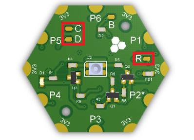
The Serial Wire Debug (SWD) interface enables fast firmware update as well as real-time debugging. You will need an STM32-compatible programmer/debugger (e.g., ST-LINK or the Nucleo board) and a programming software tool (e.g., ST-LINK Utility or via KEIL uVision IDE). Three module pads are needed for connection (plus GND): C (SWD Clock), D (SWD Data) and R (MCU Reset).
![]()
You will need to make the following connections between the programmer and the module (example provided for Nucleo programming header CN4):
- Pin 2 (starting up) >> C.
- Pin 4 >> D.
- Pin 5 >> R.
- You need to connect GND between ST-LINK and the module. If your module is powered from a USB-UART cable connected to the same laptop that you connect the ST-LINK to, then they both have a common ground and you might not need a separate GND connection.
Note: The ST-LINK Utility loads binary files while uVision loads AXF files. You can use ARM fromelf.exe tool to convert AXF files in binary ones.
![]()
-
How to make a pre-built array topology file
04/03/2018 at 03:30 • 0 commentsInter-array communication in Hexabitz is done using a routing table stored in a special header (.h) file. This header file describes the number of modules and how they are connected to each other as well as other important information for the array, hence, it is called a topology header file. Currently, you need to make a topology file manually (by modifying an existing one) or ask the array generate it dynamically with the explore command and API. Later, we might provide a software tool to generate topology files especially for complex arrays. It is still a good practice, though, to go through creating a topology file for a simple array to help you understand the process.
An example topology header file is available here. It represents the array below.![]()
What is inside a topology header file?
- File name and version comment block: Modify to identify your file. It has no effect on operation.
/* BitzOS (BOS) V0.0.0 - Copyright (C) 2017 Hexabitz All rights reserved File Name : topology_1.h Description : Array topology definition. *//* Define to prevent recursive inclusion -------------------------------------*/ #ifndef __topology_1_H #define __topology_1_H #ifdef __cplusplus extern "C" { #endif- Define number of modules in the array (only programmable modules).
#define _N 8 // Number of array modules- Define module IDs: Add one line for each programmable module in the array. IDs must be sequential.
// Array modules #define _mod1 1<<3 #define _mod2 2<<3 #define _mod3 3<<3 #define _mod4 4<<3 #define _mod5 5<<3 #define _mod6 6<<3 #define _mod7 7<<3 #define _mod8 8<<3- Array topology (routing table): Modify based on your array shape and configuration. Each line for a single module. First value is module PN (note the underscore in the beginning). The next six values represent the six array ports of a hexagon. When a value is 0, the module port is not connected. A value of _modx|Py means this port is connected to port Py of module x. For example, last value in module 1 line means that P6 of module 1 is connected to P4 of module 3.
// Topology static uint16_t array[_N][7] = { { _H01R0, 0, 0, 0, _mod2|P5, 0, _mod3|P4}, // Module 1 { _H01R0, 0, 0, _mod4|P6, 0, _mod1|P4, 0}, // Module 2 { _H01R0, 0, 0, 0, _mod1|P6, 0, _mod5|P3}, // Module 3 { _H01R0, 0, 0, _mod6|P6, _mod7|P6, 0, _mod2|P3}, // Module 4 { _H01R0, 0, 0, _mod3|P6, 0, _mod7|P4, _mod8|P3}, // Module 5 { _H01R0, 0, 0, 0, 0, _mod7|P1, _mod4|P3}, // Module 6 { _H01R0, _mod6|P5, 0, _mod8|P4, _mod5|P5, 0, _mod4|P4}, // Module 7 { _H01R0, 0, 0, _mod5|P6, _mod7|P3, 0, 0} // Module 8 };- Port directions for duplex communication: As mentioned in the hardware architecture here, array ports’ default configuration is TXD on top and RXD on bottom to allow full modularity. Ports cannot be connected, however, before swapping the polarity on one of them (since the TXD of one port should connect to the RXD of the other one and vice versa) unless single-line, half duplex communication is desired. You should add a similar section for each programmable module. The first line defines module PN (note the absence of underscore here). Subsequent lines define port polarity. normal is the default configuration (TXD top and RXD bottom) while reversed is the other way (RXD top and TXD bottom). Note that only one of the two connected ports must be reversed. It’s also preferable to leave all the unconnected ports to normal configuration. Usually, I start with module 1 by declaring all its ports normal, and then proceed to its neighbors declaring upstream ports normal and downstream ones reversed.
// Configurations for duplex serial ports
#if ( _module == 1 )
	#define	H01R0	1
	#define	_P1pol_normal	1
	#define	_P2pol_normal	1
	#define	_P3pol_normal	1
	#define	_P4pol_normal	1
	#define	_P5pol_normal	1
	#define	_P6pol_normal	1
#endif
#if ( _module == 2 )
	#define	H01R0	1
	#define	_P1pol_normal	1
	#define	_P2pol_normal	1
	#define	_P3pol_normal	1
	#define	_P4pol_normal	1
	#define	_P5pol_reversed	1
	#define	_P6pol_normal	1
#endif
How to enable/disable a topology file?
You can add the topology header file to your project by un-commenting its include directive in BOS.h and replacing it with the file name:
/* Array topology */
#include <topology_1.h>
Modules can then be added to the same project using uVision Targets feature. Click on Manage Project Items >> New (insert) Project Targets and name them with module IDs to identify them. You can choose the current target from the Select Target drop-down menu. One important step after that is to go to each target and modify the following:
- Options for Target >> C/C++ >> Define Preprocessor Symbols: Modify H01R0 to module PN and _module=1 to module ID.
- Options for Target >> Output >> Name of Executable: Modify to match module ID.
Once done, you can click on Batch Build and select all modules then Rebuild them all. We suggest to always do batch rebuild (and not build) before loading the code to make sure you don’t load an old one.
-
Code Overview 4: Data Logs
04/03/2018 at 03:10 • 0 commentsSome modules like the mircoSD memory card module H1BR60 (previously H05R00) feature permanent logging functionality to a micro-SD card. You can create up to 10 simultaneous logs with up to 30 different variables across all logs. Logs are tabulated text files that consist of a header section, a bunch of columns, each representing a single logged variable and a bunch of rows, each representing the variables’ value at a given moment. Logs have two types: RATE and EVENT. The former type logs variable state periodically at a fixed rate, while the latter logs only a state change. Below is an example of RATE log
Datalog created by BOS V0.1.0 on H05R0Log type: Rate @ 10.00 Hz
Count    Float    UINT 32
1    120.400002    1123077325
2    120.400002    1123077325
3    120.400002    1123077325
4    120.400002    1123077325
5    120.400002    1123077325
6    120.400002    1123077325
And this is an example of an EVENT log:
Datalog created by BOS V0.1.0 on H05R0Log type: Events
Count,Switch 3 (E-stop)
11,RELEASED_FOR_2_SEC
21,CLICKED
31,CLICKED
41,PRESSED_FOR_1_SEC
59,RELEASED_FOR_2_SEC
65,CLICKED
Use this API to create a new log:
Module_Status CreateLog(const char* logName, logType_t type, float rate, delimiterFormat_t delimiterFormat, indexColumnFormat_t indexColumnFormat,const char* indexColumnLabel)
where:
- logName: Log file name (without extension).
- type: Log type (RATE or EVENT)
- rate: Logging rate in Hz (max 1000 Hz).
- delimiterFormat: (FMT_TAB, FMT_COMMA)
- indexColumnFormat: Index column (first column) format (FMT_SAMPLE, FMT_TIME)
- indexColumnLabel: Index column label text.
This API returns:
- H05R0_OK: Log created successfully.
- H05R0_ERR_LogNameExists: Log already exists on card.
- H05R0_ERR_WrongParams: Wrong log parameters.
- H05R0_ERR_SD: SD card failure.
- H05R0_ERR_MaxLogs: Maximum number of logs reached.
Once a log has been created, you can add new variables to the log using this API:
Module_Status LogVar(const char* logName, logVarType_t type, uint32_t source, const char* ColumnLabel)
where:
- logName: Log file name (without extension).
- type: Log variable type (PORT_DIGITAL: log any array port as a digital input (TXD or RXD pin), PORT_DATA: log any array port as a serial data port, PORT_BUTTON: log any button/switch connected to array ports, MEMORY_DATA_UINT8, MEMORY_DATA_INT8, MEMORY_DATA_UINT16, MEMORY_DATA_INT16, MEMORY_DATA_UINT32,MEMORY_DATA_INT32, MEMORY_DATA_FLOAT: log any Flash/RAM memory location with a given data type).
- source: log variable source (P1 .. Px if type is PORT_DATA; B1 .. Bx if type is PORT_BUTTON; P1TXD .. PxTXD or P1RXD .. PxRXD if type is PORT_DIGITAL; 32-bit memory address if type is MEMORY_DATA).
- ColumnLabel: Variable column label text.
This API returns:
- H05R0_OK: Log created successfully.
- H05R0_ERR_LogDoesNotExist: Log was not found.
- H05R0_ERR_MemoryFull: Cannot allocate enough MCU memory for this variable (EVENT type logs only).
- H05R0_ERR_MaxLogVars: Maximum number of logged variables reached.
Adding a variable to a log does not start the logging process automatically. You can use the StartLog(), StopLog(), PauseLog() and ResumeLog() APIs to control the logging process for each log independently. You can also delete a log from the uSD card using DeleteLog() API. Note: If the module booted without a uSD card (or with a malfunctioning one), the logging functionality will be aborted and the indicator LED will blink indefinitely. Just replace the card and reboot again to resume normal operation.
-
Code Overview 3: Buttons/Switches
04/03/2018 at 03:07 • 0 commentsYou can connect any mechanical button or switch to any of the array ports using the following API:
BOS_Status AddPortButton(uint8_t buttonType, uint8_t port)
where buttonType can be:
- MOMENTARY_NO: A momentary tactile (push button) switch - naturally open.
- MOMENTARY_NC: A momentary tactile (push button) switch - naturally closed.
- ONOFF_NO: A toggle (ON/OFF) switch - naturally open.
- ONOFF_NC: A toggle (ON/OFF) switch - naturally closed.
Once a button has been defined, it will be saved to EEPROM and configured automatically each time on startup. You can also use the following API to remove a button and delete its definition from EEPROM:
BOS_Status RemovePortButton(uint8_t port)
Current button status can be accessed via button[i].state where i is port number. (You can refer to a button connected at port P1 with B1 and so forth.) A button status could be one of the following states:
OFF
ON
OPEN
CLOSED
CLICKED
DBL_CLICKED
PRESSED
RELEASED
PRESSED_FOR_X1_SEC
PRESSED_FOR_X2_SEC
PRESSED_FOR_X3_SEC
RELEASED_FOR_Y1_SEC
RELEASED_FOR_Y2_SEC
RELEASED_FOR_Y3_SEC
Once a button/switch is defined, you can configure it to trigger certain events using this API:
BOS_Status SetButtonEvents(uint8_t port, uint8_t clicked, uint8_t dbl_clicked, uint8_t pressed_x1sec, uint8_t pressed_x2sec, uint8_t pressed_x3sec, uint8_t released_y1sec, uint8_t released_y2sec, uint8_t released_y3sec)
- port: array port where the button is attached (P1 .. Px or B1 .. Bx).
- clicked: Single click event (1: Enable, 0: Disable)
- dbl_clicked: Double click event (1: Enable, 0: Disable)
- pressed_X1sec, pressed_X2sec, pressed_X3sec: Press time for events X1, X2 and X3 in seconds. Use 0 to disable the event. This is a latching event.
- released_Y1sec, released_Y2sec, released_Y3sec: Release time for events Y1, Y2 and Y3 in seconds. Use 0 to disable the event. This is a latching event.
These events can be linked to user callbacks to execute some tasks. Add the following callbacks to your code in main.c to make use of button events:
void buttonClickedCallback(uint8_t port)
{    }
void buttonDblClickedCallback(uint8_t port)
{    }
void buttonPressedForXCallback(uint8_t port, uint8_t eventType)
{    }
void buttonReleasedForYCallback(uint8_t port, uint8_t eventType)
{    }
where eventType is:
PRESSED_FOR_X1_SEC
PRESSED_FOR_X2_SEC
PRESSED_FOR_X3_SEC
RELEASED_FOR_Y1_SEC
RELEASED_FOR_Y2_SEC
RELEASED_FOR_Y3_SEC
Note: You can clear a latching event using resetButtonEvent() API which takes the port (i.e., button) number and event type.
CLI Support
Buttons/switches functionality is available through the CLI as well. You can use the conditional if ... end if Command Snippet to link a button event to another Command.
-
Code Overview 2: EEPROM Emulation
04/03/2018 at 03:06 • 0 commentsHexabitz modules do not have a dedicated EEPROM for non-volatile (i.e., permanent) storage. The MCU Flash memory, however, is used to emulate an actual EEPROM to store system and user parameters. The main different between the MCU Flash and an EEPROM is that EEPROMs usually allow atomic access, i.e., storing, modifying and deleting a single byte/halfword/word, while MCU Flash memory can be erased only page by page (one page is 2 Kbytes in STM32F09 MCUs). A dedicated code in BOS_eeprom.c/.h solves this problem by using a double-page system and handles all operation in the background (initialization, addressing. memory-wear leveling, etc.) The MCU Flash memory can retain data up to 10-20 years and guarantee up to 10000 erase cycle (i.e., 10000 EEPROM variable updates).
Current emulated-EEPROM has a capacity to hold up 1024 variables, each with 16-bit size and 16-bit virtual address. The BOS reserves at least 200 variables for system parameters. Users can use any remaining space to store non-volatile data. You can check out available virtual addresses in BOS_eeprom.h as shown below. Note that virtual addresses are arbitrary and they do not have to be adjacent as long as they are unique (and separated by enough distance in case the variable is larger than 16 bits).
/* EEPROM virtual addresses - Consider MaxNumOfModules is 25 */
#define _EE_NBase                 1
#define _EE_portDirBase           2    // Move to RO - 25 modules
#define _EE_aliasBase             28    // 25 modules
#define _EE_DMAStreamsBase        159
#define _EE_ButtonBase            167    // 4 * MaxNumOfPorts (10) variables for buttons: port(4 bits), type (4 bits), events (8 bits), pressed_for_x_1 (8 bits), released_for_y_1 (8 bits), etc.
#define _EE_EmptyVarBase          207
#define _EE_ParamsBase            500    // Parameter base: BOS response
#define _EE_ParamsDebounce        501    // Parameter: Button debounce
#define _EE_ParamsSinClick        502    // Parameter: Button single click
#define _EE_ParamsDblClick        503    // Parameter: Button double click (inter-click min and max)
To add a new variable, just assign a unique virtual address in project.h:
#define _EE_MyVar 207
Use the following API to store a new value to the emulated-EEPROM:
status = EE_WriteVariable(VirtAddVarTab[_EE_MyVar], MyVarValue);
The write API returns a 16-bit status:
- 0x0000: Variable was written successfully.
- 0x00AB: No valid page was found.
- Any other codes: Flash write failed.
Read the stored value using this API (where &MyVarValue is the address of your variable in RAM):
status = EE_ReadVariable(VirtAddVarTab[_EE_MyVar], &MyVarValue);
It returns another 16-bit status:
- 0x0000: Variable was found and read successfully.
- 0x0001: Variable was not found.
- 0x00AB: No valid page was found.
-
Code Overview 1: Array Messaging
04/03/2018 at 03:05 • 0 commentsI'll start a series of logs titled Code Overview to go over some areas in Hexabitz code in more detail. Here's the first one.
Messaging Protocol
Messaging in the array is carried out via short unacknowledged packets in the following format (each field is a single byte):
| Length || Destination | Source | Code | Code | Par. 1 | Par. 2 | ------- | CRC ||
- The Length byte is sent first. After that the message is sent. Message length includes all message bytes including the CRC (without the length byte itself).
- Maximum message length is 50, i.e., maximum number of parameters per message is 45 bytes.
- Message length cannot be 0x0D = 13. If message length is 13, i.e., parameters are 8 bytes, then the message is padded with extra zero parameter to make the length 14.
- Source and destination are IDs of source and destination modules.
- If destination is 255 = 0xFF, the message is a broadcast.
- If destination is 254 = 0xFE, the message is a multi-cast (going to a group).
- If destination is 0, the message is sent to an adjacent neighbor only.
- CODE is a 16-bit variable with the following format:
- 16th bit (MSB): a flag for long messages. If 1, then message parameters continue in the next message.
- 15th bit: a flag to enable/disable Message only response.
- 14th bit: a flag to enable/disable CLI only response. (note that to enable this bit, bit 15 must be enabled as well).
- 13th bit: a flag to enable TRACE mode (visually trace message route).
- Bits 1-12: Message codes. Maximum number of message codes is 212 - 1 = 4095.
- Long messages can be broken down into maximum of 20 messages, i.e., 900 bytes of parameters. Any payload larger than 900 bytes will have to setup a DMA stream.
- The CRC byte is not implemented yet. Right now it has a fixed value of 0x75. It will be replaced later with CRC8 of the message.
Messaging Workflow:
- Source module builds a message in the form shown above.
- Source sends one byte representing the message length and waits for 1.5 msec.
- Destination receives the length byte (in the UART_RxCpltCallback) and activates a port-to-memory DMA stream to transfer the same amount of bytes requested. Once finished, receive interrupt is activated on this port again.
- After destination receives the last termination byte (0x75 or CRC), it executes UART_RxCpltCallback again and notifies the appropriate messaging task.
- Messages are parsed to read source, destination and code bytes. Received message length is checked againts the Length byte.
- If the message is a transit message, it'll be forwarded directly. If it's a broadcast message, it will be broadcasted and then processed.
- Messages are processed according to their message codes. After that buffers are cleared and receive interrupt is activated on this port again.
- Message response and TRACE flags are verified to generate the appropriate response.
- If the message is long, the longMessage flag is activated and can be used to concatenate consecutive payloads before processing them.
Routing
You can send Messages through the array using the following APIs. The first API sends a Message out a given port to the adjacent module. It is useful when you do not know your neighbor’s ID or you simply want to send something across all or some ports:
BOS_Status SendMessageFromPort(uint8_t port, uint8_t src, uint8_t dst, uint16_t code, uint16_t numberOfParams)
where port is the output port, src and dst are source and destination module IDs, code is the Message code and numberOfParams is number of Message parameters. If the Message is originating from this module, you can use src=myID. The next API sends a Message to a another module (whether adjacent or not) :
BOS_Status SendMessageToModule(uint8_t dst, uint16_t code, uint16_t numberOfParams)
where dst is the destination module (source is always the current module), code is the Message code and numberOfParams is number of Message parameters. SendMessageToModule() API basically calculates the optimal route to destination and which port leads to that route and then calls SendMessageFromPort() to send the Message from that port. Using 0xFF or BOS_BROADCAST for destination, broadcasts the Message to the entire array. You can control response settings of a unicast or broadcast Message via the BOS.response parameter:
- BOS_RESPONSE_ALL: Enable response on all Messages.
- BOS_RESPONSE_MSG: Disable response on remote CLI Commands and enable on other Messages.
- BOS_RESPONSE_NONE: Disable response on any Message.
Before you call one of the APIs above to send a Message with parameters, you need to fill out the parameters array first:
messageParams[0] = (uint8_t)(600000>>8); messageParams[1] = 2; messageParams[2] = FORWARD;etc..
Array topology (routing table) is saved in the two-dimensional array variable array, which will be either provided in the topology header file or generated by Explore()API. Learn more about topology header files here. The FindRoute() API utilizes Dijkstra's shortest path algorithm to calculate the optimal route between two modules in the array based on the pre-populated routing table:
uint8_t FindRoute(uint8_t sourceID, uint8_t desID)
To avoid sending redundant routing information with each Message, this API returns the module port (P1 .. Px) closest to destination module. The Message is sent through this port to the next module in the chain which runs the FindRoute() API again and forwards the Message until it reaches its destination. As mentioned above, you can call the SendMessageToModule() API and it will take care of the entire process.
-
Hexabitz Module Factsheet a.k.a. Documentation
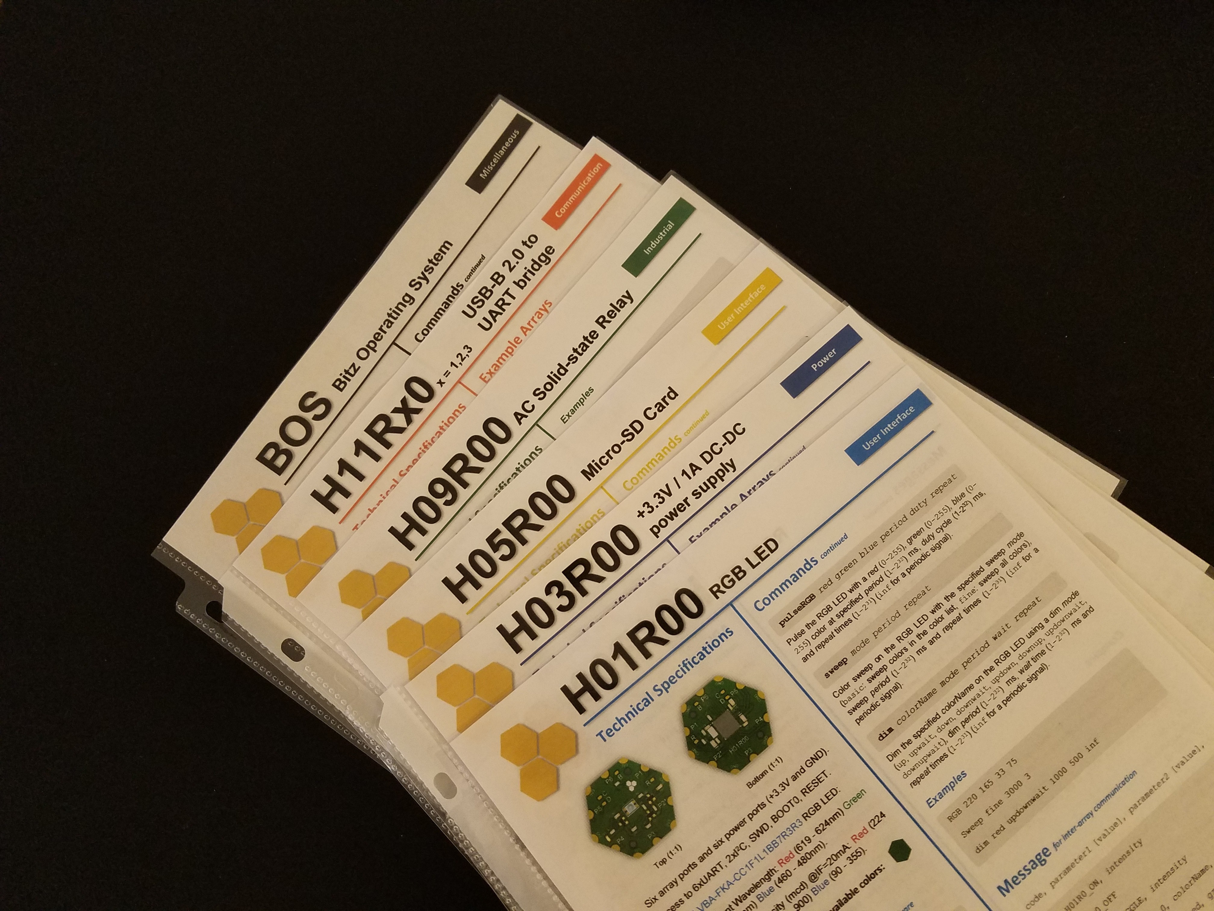
04/03/2018 at 02:58 • 0 commentsFactsheets are Hexabitz's take on documentation! They're a mix between a hardware datasheet and a software cheatsheet. They should get you up to speed on any module and provide quick access to the most needed information, e.g., major component part numbers, module APIs and Commands, etc. The software section features some simple examples as well to provide quick help with the syntax. Factsheets are designed to be printed double-sided and kept in nylon sheet covers so that they're easily accessible when you need them.
![]()
Each module factsheet should generally contain the following information:
- Module name (part number) and short description.
- Technical specifications for major module components including available array ports, connectors, etc.
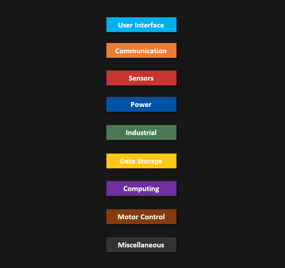
- Module general classification (color-coded category). Please check below.
- Factsheet release date.
- If a module is programmable, the factsheet contains the following software parts as well:
- Module CLI Commands. Note that BOS Commands are not included here rather in a separate factsheet dedicated for BOS. (Same thing also for BOS Messages and APIs.)
- Module Messages and Message Codes.
- Module APIs.
- Software release version that corresponds to this factsheet version.
Factsheets are available in the project files section.
Module Categories
Hexabitz modules are usually organized in the following categories. The factsheets are color-coded according to these categories to help you classify them quickly:
-
Module Naming (Part Numbers)
04/03/2018 at 02:56 • 0 commentsHexabitz modules’ part numbers follow this naming convention:
HxxRyz (-E)
where:
- H: is module shape prefix. Available shapes are: H (hexagon), P (pentagon), T(triangle) and S (square). Note that some modules might repeat the same shape to gain more surface area, e.g., two hexagons or two squares permanently connected to each other. They still get a single prefix from the list above.
- xx: is the main functionality (front-end) code, e.g., 01 for LEDs. This number is hexadecimal to support 256 main functionalities.
- R: is a separator that separates main functionality and sub-functionality codes.
- y: is the sub-functionality (front-end) code. This number is hexadecimal as well and thus the number of total functionalities supported is 16 x 256 = 4096.
- z: is module hardware revision number. Older revisions will be depreciated.
- -E: This is an optional extension used in some part numbers to define a deviation from standard hardware specifications (e.g., flex PCB or non-green silkscreen or different connectors).
 Hexabitz