-
Modules
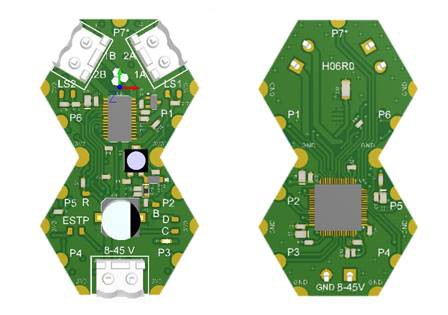
04/02/2018 at 01:59 • 0 commentsThis is the list of available and planned Hexabitz modules. We will update regularly as things change :)
Module Stages
Each Hexabitz module goes through six different stages from its inception to mass production:
Concept The module functionality is laid out and major components chosen.
Design Hardware design is complete.
Testing Module is prototyped and being tested.
Alpha Initial firmware and hardware are ready for a limited public release.
Beta Expanded public release with production-ready hardware and mature firmware.
Production Module is mass produced and firmware is stable.
![]()
Note: Some module names (part numbers) have changed. The list below shows new and old names. When there is a conflict, the old name is listed between parenthesis.
Modules
H00R00
Silkscreen artwork / logo
Stage: Alpha
![]()
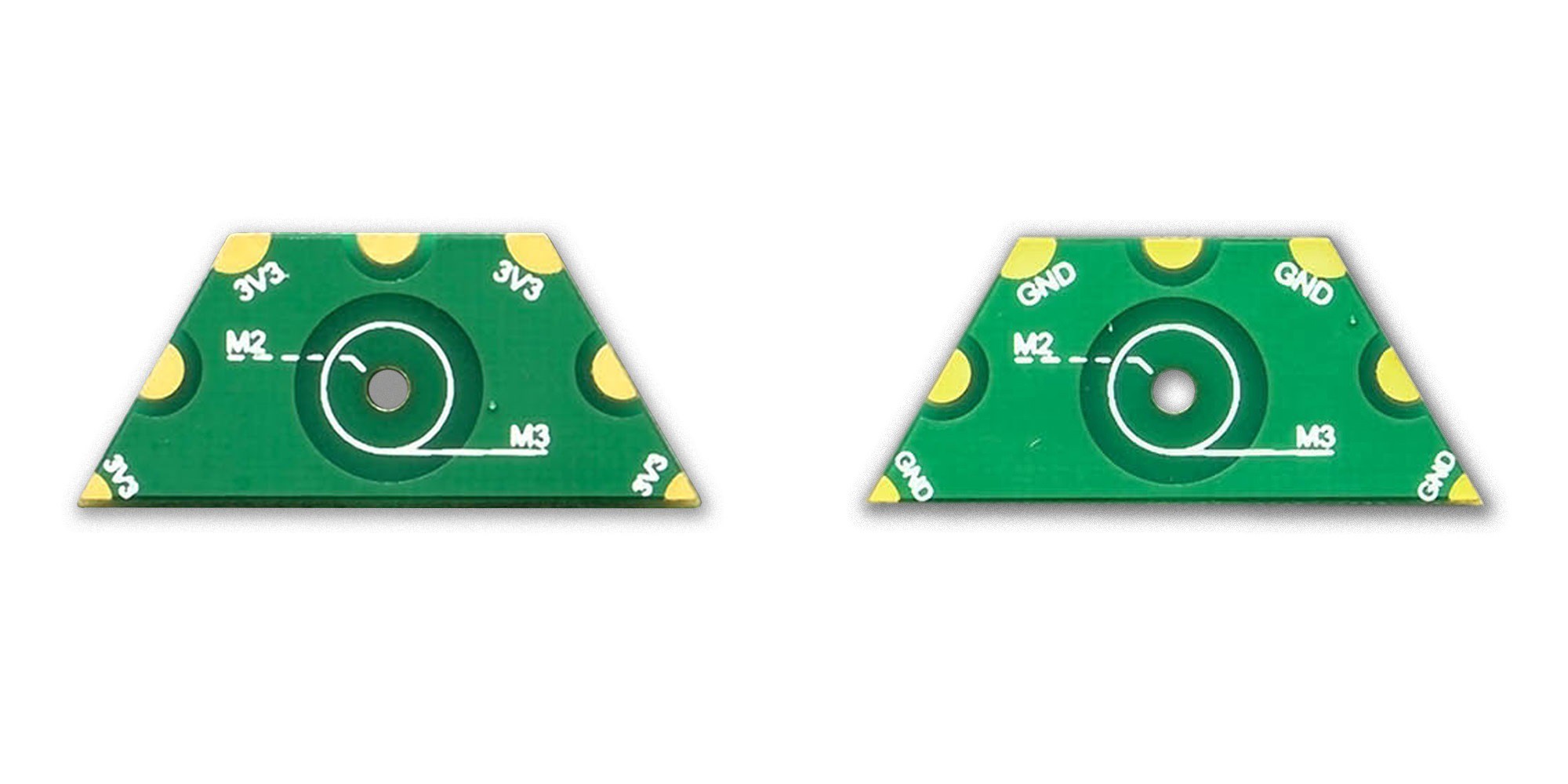
H00R00-M
M2/M3/M4 mounting hole
Stage: Alpha
![]()
H00R00-H
Silkscreen artwork / logo
Stage: Alpha
![]()
H00R00-MH
M2/M3/M4 mounting hole
Stage: Alpha
![]()
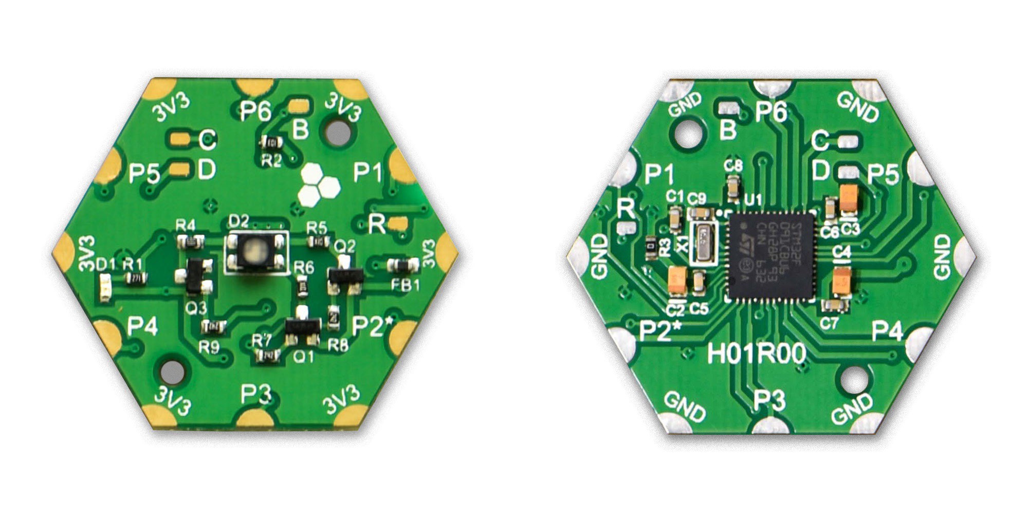
H01R00
RGB LED
Stage: Alpha
![]()
H01R20
3 x RGB LED
Stage: Design
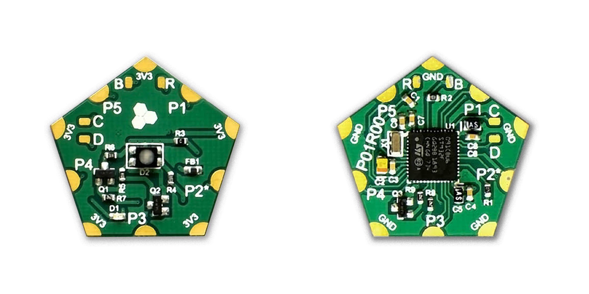
P01R00
RGB LED
Stage: Alpha
![]()
H03R00-B
3.3V / 1A DC-DC Buck Power Supply With Barrel Jack DC Input
Stage: Concept
H03R00-T
3.3V / 1A DC-DC Buck Power Supply With Terminal Block Input
Stage: Alpha
![]()
P03R00
3.3V / 1A DC-DC Buck Power Supply With Terminal Block Input
Stage: Design
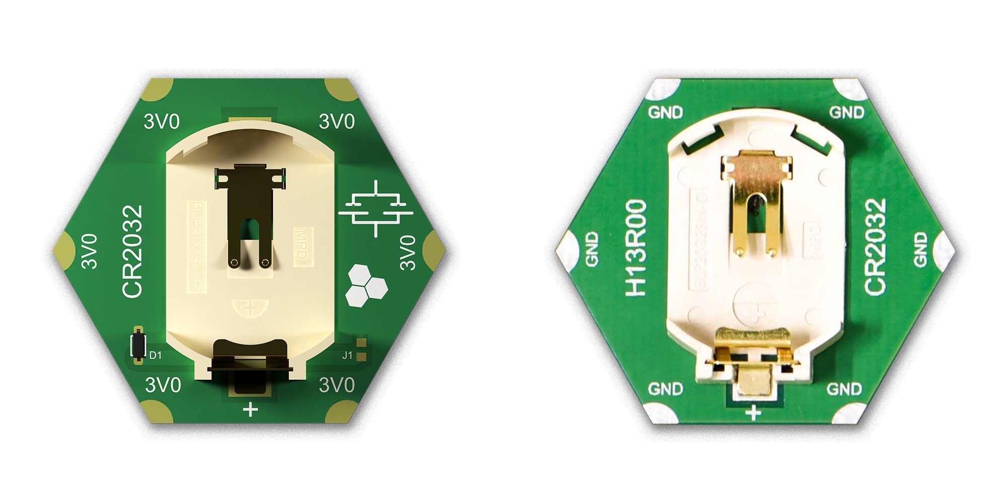
H04R10 (H13R00)
2 x CR2032 Coin Cell Lithium Battery Holder In-parallel
Stage: Alpha
![]()
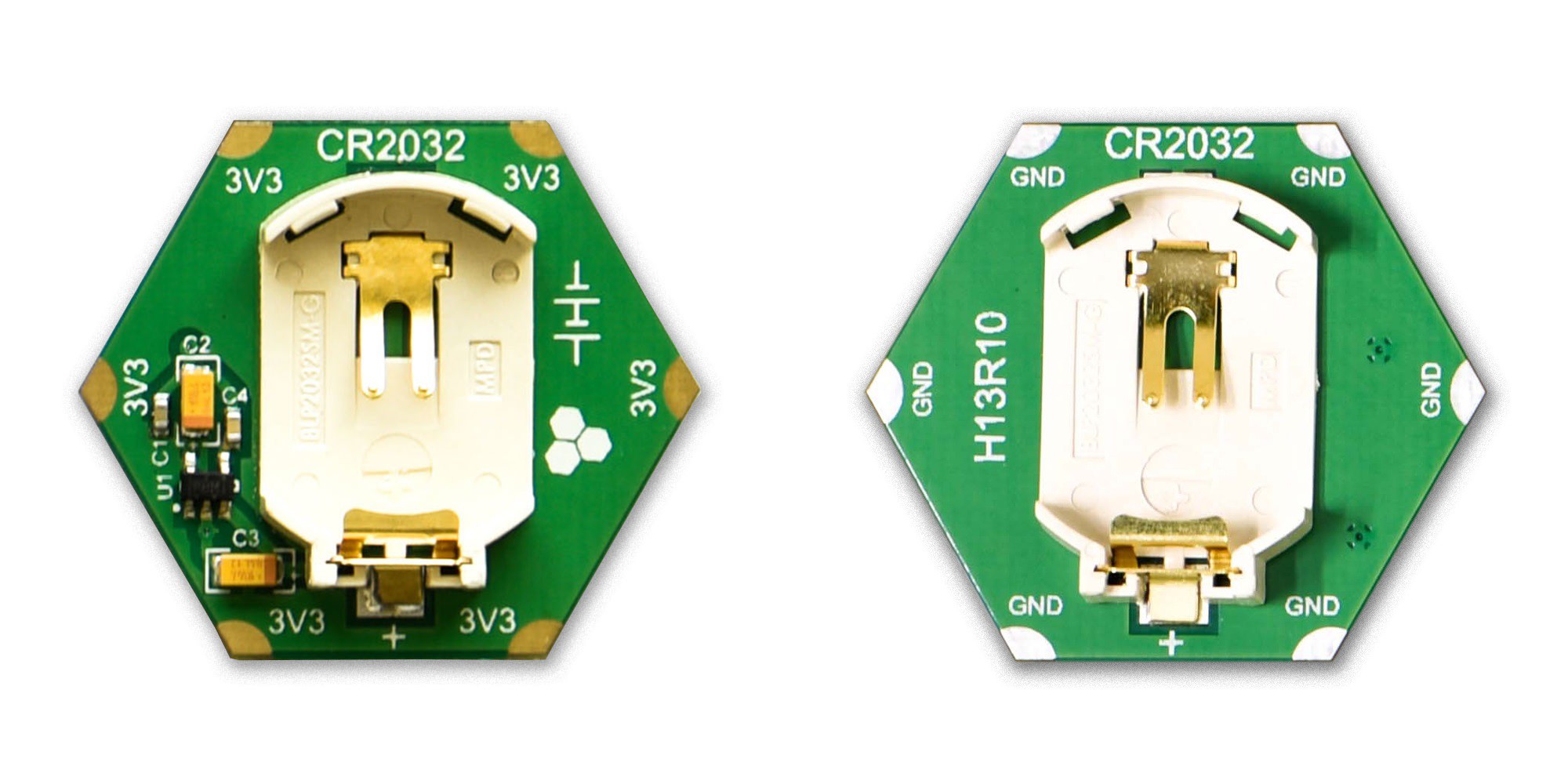
H04R20 (H13R10)
2 x CR2032 Coin Cell Lithium Battery Holder In-series
Stage: Alpha
![]()
H05R00-B
1S Lithium-Polymer Battery Charger With Barrel Jack DC Input
Stage: Concept
H05R00-C
1S Lithium-Polymer Battery Charger With USB-C Input
Stage: Concept
H05R00-M
1S Lithium-Polymer Battery Charger With Micro USB-B Input
Stage: Concept
H05R00-T
1S Lithium-Polymer Battery Charger With Terminal Block DC Input
Stage: Concept
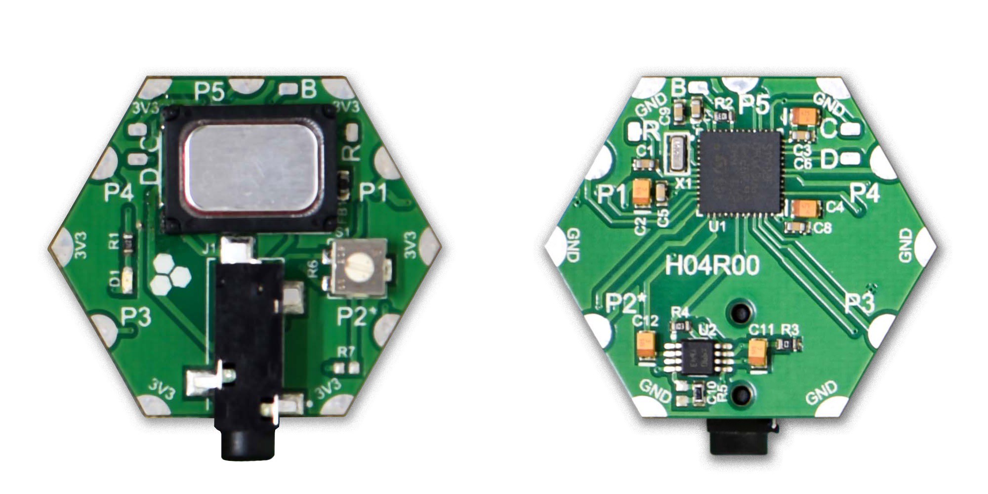
H07R30 (H04R00)
Audio Speaker and Headphone Jack
Stage: Testing
![]()
P07R10
Audio Speaker
Stage: Design
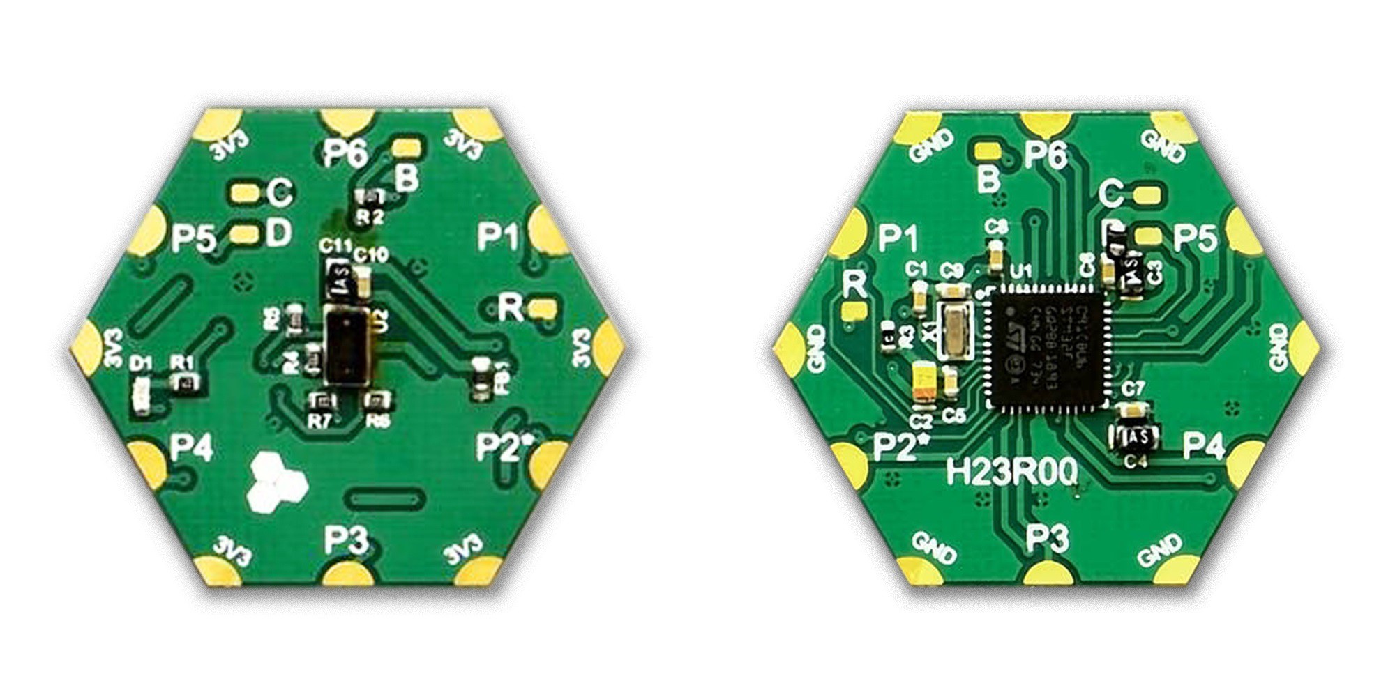
H08R60 (H23R00)
Time-of-flight IR Sensor
Stage: Alpha
![]()
H09R00
Thermocouple Temperature Sensor
Stage: Design
H0AR30
MEMS Microphone
Stage: Design
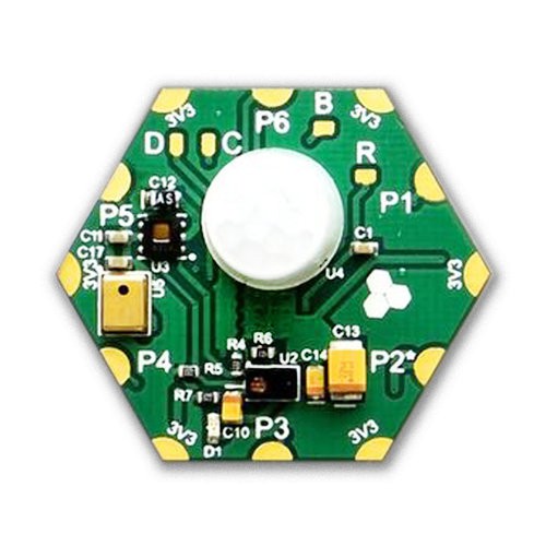
H0AR90 (H12R00)
Sensor Hub (Temperature, Humidity, Ambient Light, Color, Microphone, IR Motion Detector)
Stage: Testing
![]()
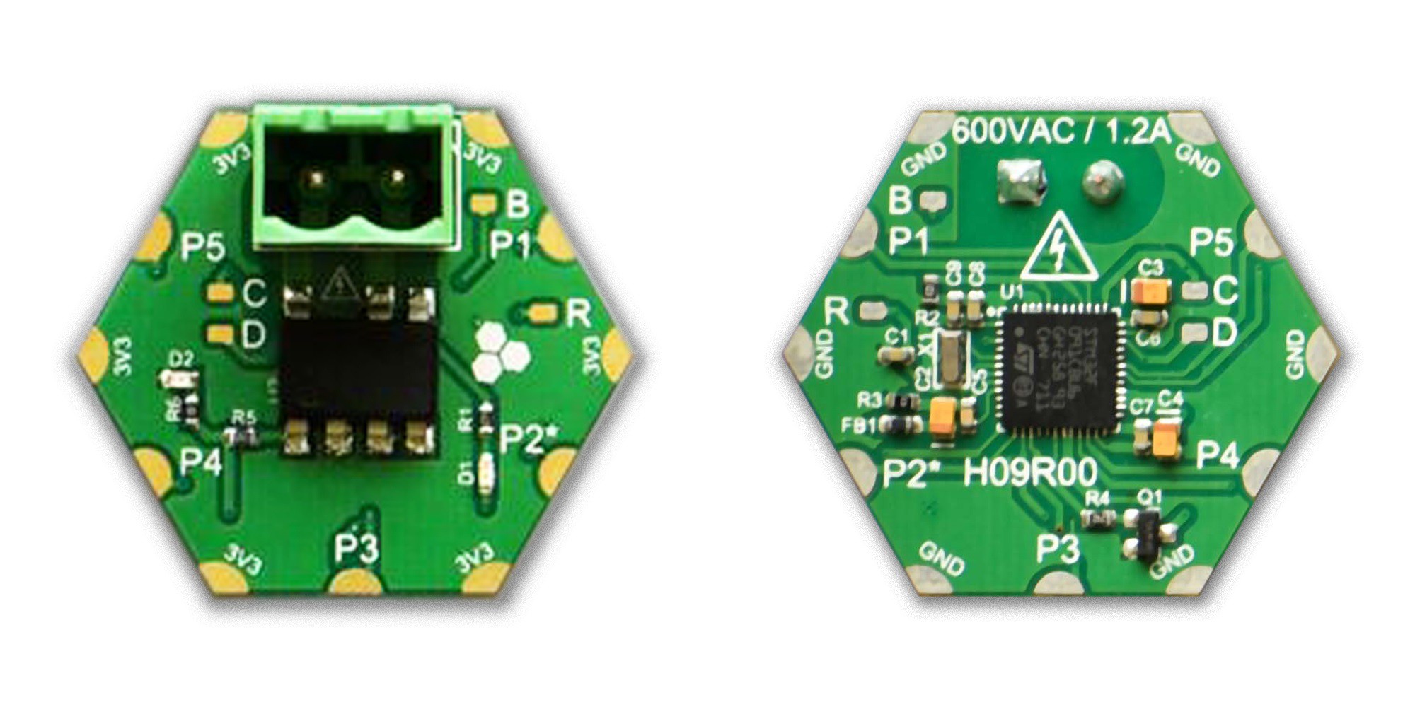
H0FR60 (H09R00)
600 VAC / 1.2A Solid State Relay
Stage: Alpha
![]()
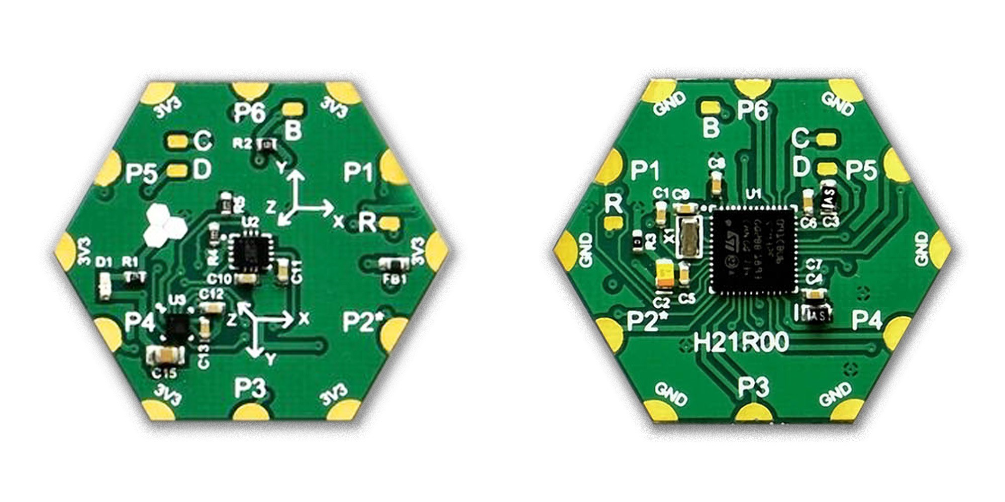
H0BR40 (H21R00)
3-axis Inertial Measurement Unit (IMU) + 3-axis Digital Compass
Stage: Testing
![]()
H10R40
Thumb Joystick
Stage: Design
H12R00-V
Industrial Analog Input 0-10V / 0-5V
Stage: Testing
H12R00-I
Industrial Analog Input 4-20mA
Stage: Testing
H13R70
8-input Industrial Digital Serializer
Stage: Design
H17R00
3A Stepper Motor Drive
Stage: Design
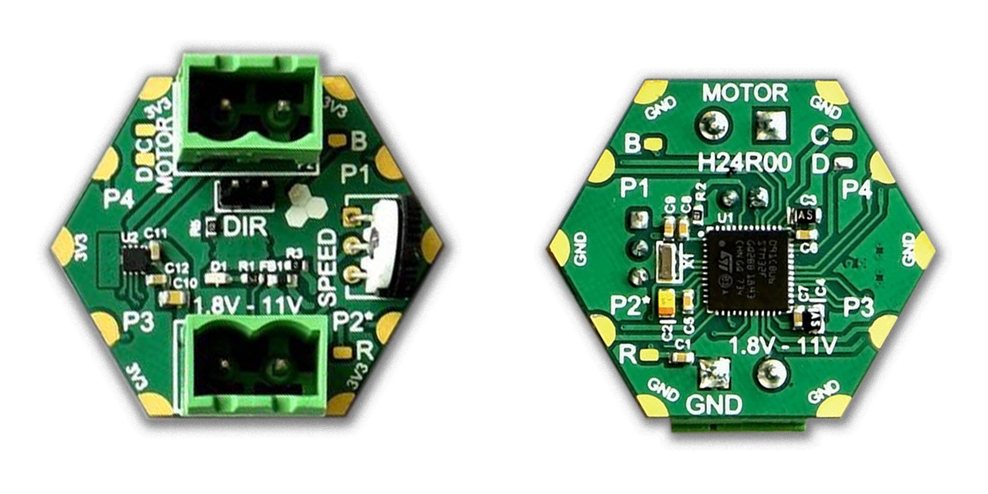
H18R00 (H24R00)
11V / 1.8A Brushed DC Motor Drive
Stage: Testing
![]()
H19R20
2.5A Sensored Brushless DC Motor Drive
Stage: Design
H1AR10 (H11R10)
USB-B-to-UART Converter
Stage: Alpha
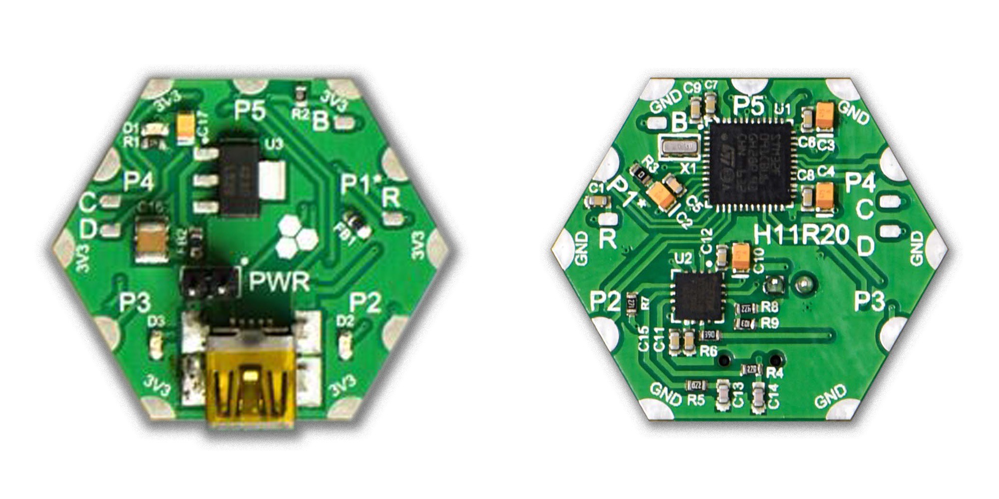
H1AR20 (H11R20)
Mini USB-B-to-UART Converter
Stage: Alpha
![]()
H1AR30 (H11R30)
Micro USB-B-to-UART Converter
Stage: Alpha
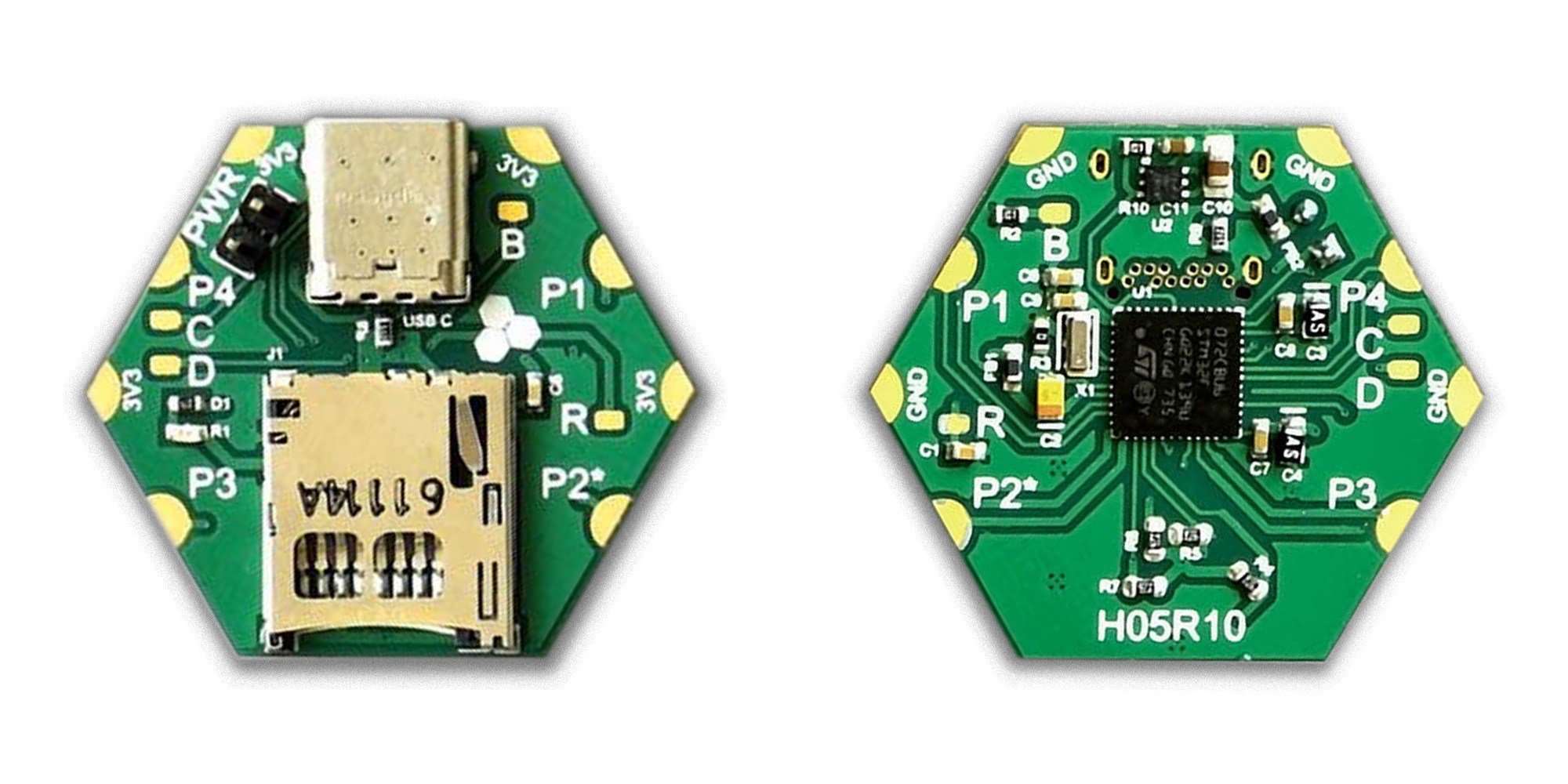
H1AR40 (H05R10)
USB-C Mass Storage Device
Stage: Testing
![]()
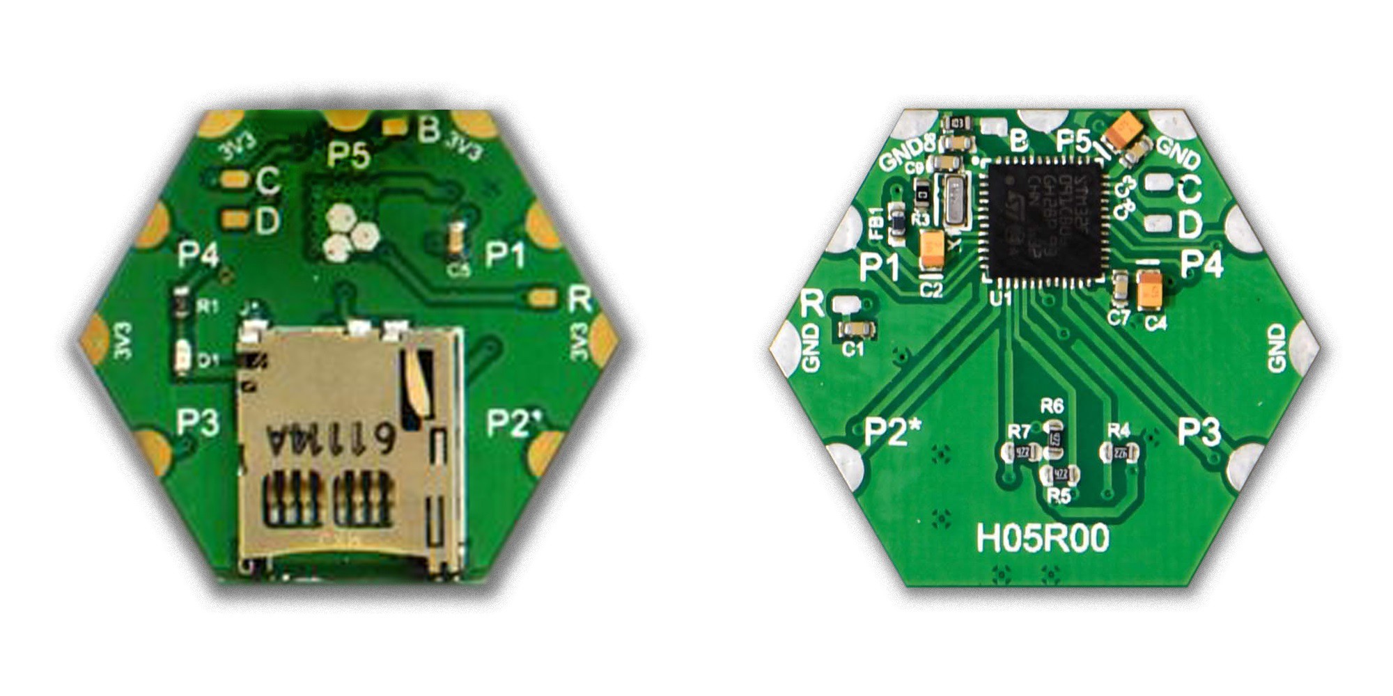
H1BR60 (H05R00)
Micro SD Memory Card
Stage: Alpha
![]()
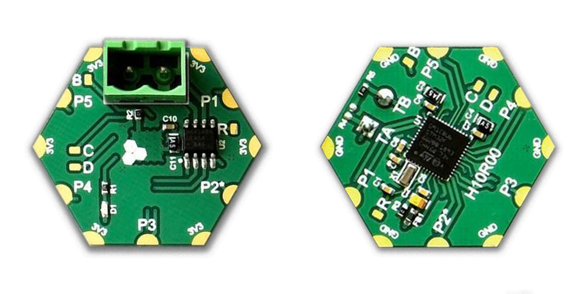
H1DR10 (H10R00)
RS485 Serial Transceiver
Stage: Testing
![]()
H1DR20
CANBus Serial Transceiver
Stage: Design
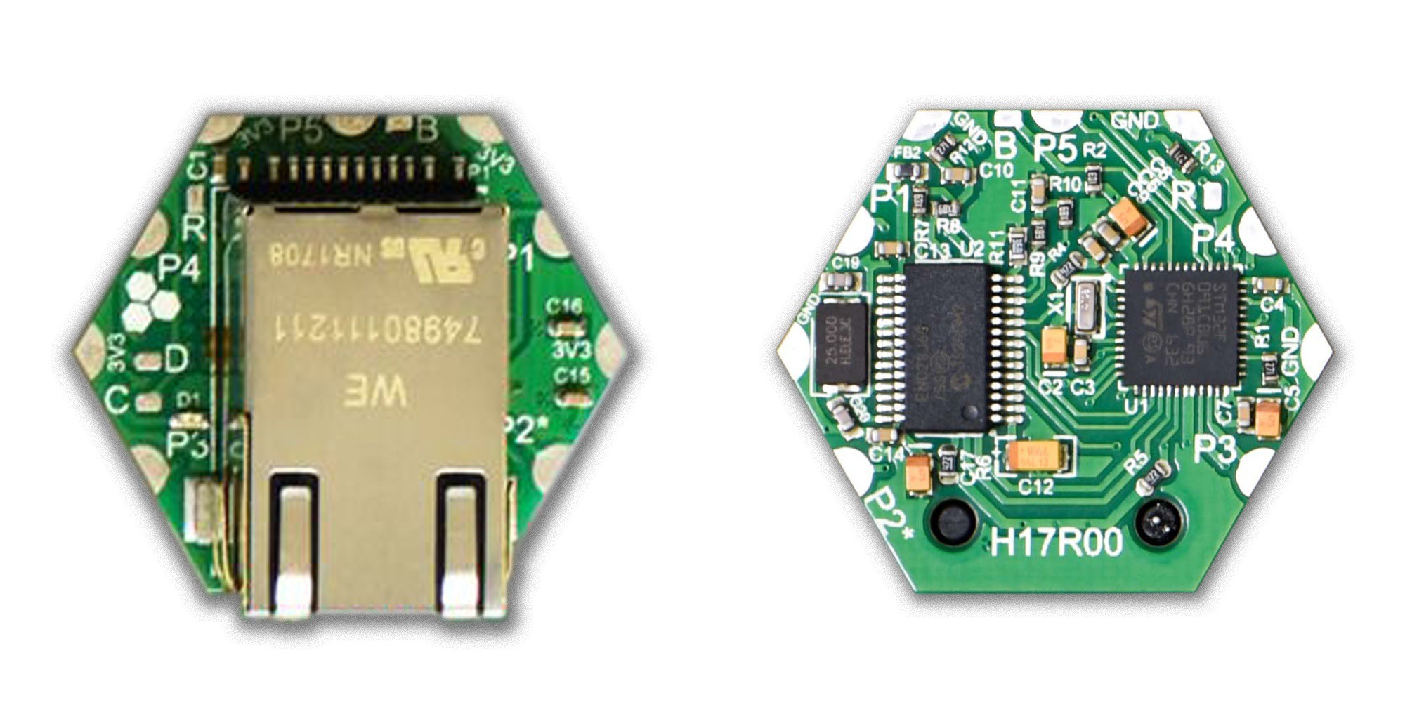
H1DR50 (H17R00)
10Base-T Ethernet
Stage: Testing
![]()
H1FR00
Sub-GHz Long Range RF
Stage: Design
H21R00
2.4 GHz Wifi
Stage: Concept
H23R00
Bluetooth V4.0 HCI
Stage: Testing
H23R10 (H02R10)
Bluetooth V4.0 Dual Mode
Stage: Alpha
![]()
H32R10
3.3V-to-5V / 1A DC-DC Boost Power Supply
Stage: Design
-
The Reason We Exist
03/20/2018 at 04:35 • 0 commentsA Void in The Market
One might think the hardware prototyping scene is quite saturated and does not accommodate new platforms. Yes and no. There's definitely a large number of platforms and options out there-which is a good thing because it enables people to innovate. However, if you look at available prototyping solutions from a different perspective, you will spot a good deal of clustering and a void in the market, which is where the need for systems like Hexabitz come from.
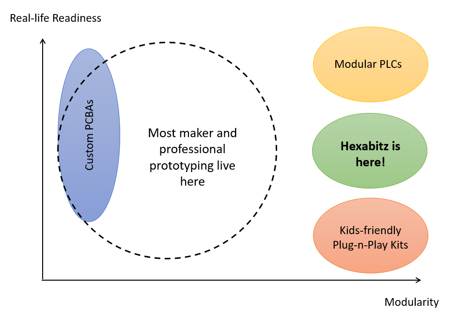
There has always been a trade-off between modularity and system's ability to support real life applications, i.e., being rigid, compact, lightweight and reliable. Although you can't combine both, current options are really limiting: you either have to settle for jungles of wires and stacked boards or build a one-time-use compact and rigid PCBA. At the two extremes, you also have a bunch of really nice modular plug-n-play solutions that are geared toward K12 and STEM education and there's the high performance, very expensive modular PLCs and industrial card-based systems. We found our sweet spot just in between! We think platforms such as Hexabitz can provide a great deal of modularity and at the same time be lightweight, rigid and compact enough to fit many in-field prototyping scenarios. It's why we focus in our platform on horizontal integration because that's how electronics and PCBAs are made in general and thus, the best form factor for many applications.
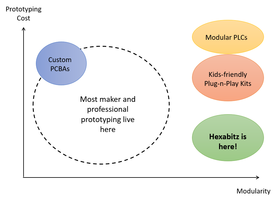
If you plot prototyping cost per unit there is another clear void. Custom-made PCBAs are usually expensive and time-consuming for small prototyping quantities. Since Hexabitz design is bare-bones, i.e., consisting of electronics and PCBs only, the cost per module can be driven down significantly at mass production enabling lower costs for prototypes and still better form-factor and rigidness than most other solutions.
But Does It Really Matter?
Why do we even need modular prototyping? Well, with 41.8 million tons of e-waste generated in 2014 and 50+ expected this year, there's enough electronics waste destroying our planet (less than 15% gets recycled)! One might say, this is mostly production waste and prototyping amounts to a minuscule part. This is true, however, makers, hobbyists and engineers consume much more PCBAs than the average consumer. We're all at fault to some degree-including myself. A typical maker might have dozens or even hundreds of custom-made PCBAs collecting dust from all sorts of projects and prototypes. With the impressive year-over-year growth of the maker movement, exemplified by the growth of Hackaday community itself and the following graph illustrating Maker Faire growth (re-purposed from here), this doesn't look sustainable!
We definitely do not call on people to abandon custom PCB design and prototyping. It's always an educational experience and lots of fun. Many times designing your own is really the only solution. However, there are definitely many occasions where you can settle down for a modular prototype.
With Hexabitz, you still get the fun of building something with your own hands when you design your own shape and solder the modules. After you're done with the project and when it starts collecting dust on your shelf, all you need is to dis-assemble the modules and reuse them again-re-cabbing your investment! If you don't have the skills or time to design professionally looking custom boards, you can still satisfy your inner-nerd and save the environment (and your pocket as well) ;-)
The Truth About Modular Electronics
You might say modular electronics projects had mixed results so far (a.k.a. failed), which is true to some extent. We personally believe many people are looking in the wrong direction. Electronics can be generally divided into two categories:
- User-facing (front-end) Electronics: These gadgets must be extremely streamlined to the user experience. They must be the lightest, the smallest, the cheapest and the most beautiful a device can be. This goes directly against modularity. Modularity, by definition, adds overhead and overhead is not bearable in such devices. Examples include smart phones, watches, wearables, consumer-facing gadgets, etc.
- Non User-facing (back-end) Electronics: These devices have less constraints for size, weight or form-factor. Users are not in direct contact with such devices. Examples include electronics inside your elevator, car, washing machine, air conditioner, etc.
Front-end devices cannot be modularized because this severely affects their functionality. Most people don't like if their phone or watch is modular but also bulky, heavy or ugly. Who are we kidding here? People won't stop buying new phones because they've got a modular one! People buy new gadgets because they like to show off.
On the other hand, back-end devices can be modularized to some extent. People don't care how the electronics inside their washing machine actually look like and many will be quite happy to know they're buying a washing machine or a fridge or car with modular and reusable electronics. It's a tough problem designing things in a modular fashion and guaranteeing quality. But If manufacturers get it right, there is a chance at least a small percentage can be reused across different products (or rebuilt into refurbished / lower-grade units).
So why everyone is building modular phones and watches? Seems like there's a new project everyday. You might say because they have the biggest impact on the environment. That's exactly the contrary. According to United Nations research study, Small IT e-waste- the category that includes phones and similar items was only 3 million tonnes in 2014, while large and small equipment (most other household items) amounted to 24.6 million tonnes combined!
Yes! Building a boring and non-flashy modular back-end electronics device is 8 times more probable to save the environment than a flashy and sexy modular phone or watch or wearable. So please no more modular phones and watches and let's focus our attention and resources into the back-end- all those boring and forgettable devices where endless opportunities for modularization exist.
Do you have you a similar / different opinion about this matter? Feel free to share with us your comments and ideas below!
-
Hexabitz Software Architecture
03/13/2018 at 03:55 • 0 commentsIntroduction
Hexabitz arrays are fully-distributed, multiprocessor systems. Each configurable module has its own MCU. Modules connect with each other to form an array, similar to the way computers connect to form a network. Having separate processors -instead of embedded multi-cores- in the same array gives you the flexibility of running them at different clock speeds or even mixing powerful, expensive processors with small and cheap ones.
This architecture dictates having a separate firmware uploaded to each module. You are required currently to write, debug and compile code for each module separately -while keeping in mind all the interactions between these modules- since there is no technology to support intuitive multi-processor software development. I’m looking forward to the day where we can write a single software -as if we were developing for a single target- and the intelligent compiler would then dissect this software into small pieces, figuring out all the required interactions between these modules on its own. Hopefully, it won’t be that long!
Until we get our hands on such a revolutionary tool, we have to figure out ways to design and develop code for complex arrays so that an array of 10 modules does not take 20x development efforts. Fortunately, there are lots of tricks and solutions to substantially reduce the amount of work needed. We will discuss some here and in future posts.
In order to support a wide array of users, Hexabitz is designed for three developer levels/personalities:
- Advanced Developers (The Do-It-Yourself Folks): Users with critical needs and very high skills in embedded systems development can take Hexabitz hardware and write their own software from scratch using low-level, third-party hardware drivers available from chip manufacturers. Being an open-source hardware system gives these hardcore users the freedom of developing their own system without the hassle of hardware design and the nightmares of production lines and supply chains!
- Experienced and Mid-level Developers (Mix-n-Match Heros): You do not have to start from scratch! We laid down the ground work for software development through our operating system (BOS), APIs and module drivers, all coupled with a set of optimized third-party middleware (e.g., real-time operating system, FAT system, etc.). Users can either use all of the above and focus on application-level development or pick the level of integration and design the components that they feel are important to differentiate their product (e.g., using only BOS or only module drivers).
- Noobs (The I-Have-No-Idea Newbies): Newbies and beginners can still utilize Hexabitz through Command Line Interface (CLI). CLI is a set of plain-English commands that you can send to the modules to execute. These commands are very handy to perform quick tests and run simple applications. In fact, probably 80% of simple applications can be executed through a set of CLI commands. The CLI command set will be expanded regularly to offer more features while preserving simplicity and easy-access as much as possible.
Any Other Options?
We will focus, in the time being, on developing and supporting hardware and software tools and components mentioned above. We will do our best to offer more options in the future, especially in higher-level programming languages (e.g., visual programming, Python, MATLAB, etc.)
Hexabitz Software Components
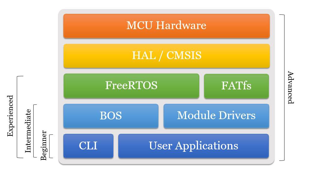
Figure 6 illustrates the hierarchy of Hexabitz software components how they map to different users. We will discuss next these components and detail the important ones.
![]()
Figure 6. Hexabitz Software Components 1. Low-level Hardware Drivers - Developed by ST & ARM
The Hardware Abstraction Layer (HAL) and the Cortex Microcontroller Software Interface Standard (CMSIS) developed by ST and ARM, respectively, are the core low-layer drivers for Hexabitz mainstream-implementation MCU hardware. They interface directly with MCU registers and perform the most basic tasks. Most developers do not need to worry about these drivers but it helps to understand how they work and how they can be implemented if you want to dig in further in embedded systems development and optimize the code for your application.
2. Third-party Middleware - Developed by various vendors
A higher-level of third-party drivers is required to perform advanced functionality such as real-time control and data storage management. Two major third-party, middleware components are currently used in Hexabitz software: FreeRTOS and FATfs. It is also very likely that we add more components in the future as functionality expands.
FreeRTOS
FreeRTOS is the de-facto real-time operating system (RTOS) for MCUs and small embedded systems. It is open-source and free to use in its standard format, thus, accessible to everyone. An RTOS is a critical tool to ensure synchronous, predictable and real-time execution of software in embedded systems. Although FreeRTOS does not have all the capabilities of a computer-grade RTOS, it does have basic multi-threading (multi-tasking), memory management and access control. FreeRTOS code is complex and difficult to understand for non-specialists. However, from a user perspective, interactions with FreeRTOS become minimal if Hexabitz’s BOS and module drivers are utilized. Currently, Hexabitz is not making use of all of FreeRTOS features but as the platform evolves, we will integrate more and more of these powerful features. In general, each module is always running the following threads (tasks) in parallel (Note that parallel here is an over-simplified notion as MCUs can only execute code serially. The FreeRTOS scheduler, however, cycles between these tasks on every RTOS beat to simulate parallel execution.)
- N Communication Tasks (where N is the number of module array ports): These tasks handle communication with other modules and external hardware via BOS messages and streams. All N tasks can run simultaneously, transmitting and receiving data, without affecting each other. Their impact on MCU performance can be effectively reduced when using DMAs.
- CLI Task: This task is responsible about communicating with human users. It handles the delay in human interaction without blocking the system. This means you can connect to the module to inquire and update its parameters and send new commands at any given time (and from any array port) without stopping or delaying front-end processing and array communication. Right now, you can only open one CLI session on the same module at any given time. You can, however, open as many CLI sessions as you want on different modules in the same array! This means you can connect to two different modules and simultaneously send two different commands across the array and they will be transferred and executed properly. It is possible to open and utilize a CLI session by non-human entity (e.g., an external hardware). However, it is much more efficient to use Messages for this.
- Default Task: This task is running in the background and is used by the BOS to execute some behind-the-scene activities such as initiating array ports scan and controlling module indicator LED.
- Module Task (optional): Some modules have their own task(s) running in the background as well. This task is concealed from the end user and is used to run various module-specific, background applications.
- Front-end Task: This empty task is exposed to the user through the project main.c file. It is essentially a scratch pad that can be customized for each project. The end-user can effectively ignore all other running tasks and treat the system as a single-thread program with the front-end task simulating the super-loop used in traditional, single-threaded, C programs.
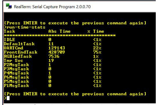
Figure 7. shows a screen capture of the CLI interface displaying tasks running in H01R00 module along with their running time (i.e., CPU utilization) percentage.
![]()
Figure 7: Tasks (threads) running in a Hexabitz module. There are six communication tasks (PxMsgTask), a CLI task (UARTCmd), a DefaultTask, a FrontEndTask and a module-specific task (RGBledTask). IDLE and Tmr Svc are tasks created by FreeRTOS for its internal use. FATfs
File Allocation Table (FAT) is a system to manage files on storage media. It is used on personal computers and many embedded systems. FATfs is a free, memory-optimized FAT module for small embedded systems. It enables you to read and write files stored on various storage media (e.g., SD/MMC cards, Flash memory, SRAM memory, etc.) and same files can be viewed or modified on personal computers as well. Storage-related modules utilize FATfs as part of their module drivers. FATfs code is highly optimized and difficult to read and understand. As with FreeRTOS, using module drivers effectively relieves the user from understanding FATfs intricacies while utilizing its features.
3. Bitz Operating System (BOS) - Developed by Hexabitz
BOS is Hexabitz own operating system, built on top of FreeRTOS, and specifically designed to support Hexabitz arrays. It relieves the user from writing code to perform initialization, inter-array communication and housekeeping tasks, among others. BOS also manages the Command Line Interface (CLI)-a simple and intuitive tool for user interaction, as well as non-volatile storage of module and array parameters (and syncing these parameters across the array). Future software releases will introduce more intelligence and automation to let users focus on their end-application and delegate all background activities to the BOS. BOS is an essential part of every Hexabitz software project. Both the BOS and module drivers have the following sub-components:
- Commands: CLI Commands are a set of easy-to-use control commands in plain-English language. They can be sent to the module from any serial terminal tool (e.g., RealTerm) via any of the array ports. Commands can be executed locally (i.e., on the module itself), forwarded to another module (or a group of modules) or broadcasted to all modules in the array. There are Commands available to control BOS and most of Hexabitz configurable modules. In general, most Commands return a textual response to the user, either from the local module or from a remote one. The response can be turned on/off by the user.
- Messages: Messages are the machine-format version of CLI Commands. They are transferred across the array in short packets that are faster and more efficient but not human-decipherable. They can be used by external hardware to control Hexabitz modules. They are also used inside the array for inter-array communication. When you send a Command to a remote module, it is forwarded to its destination via a special Message. The textual response is also a packed into another Message that is sent back to the source module, which eventually displays it to the user. As with Commands, there are specific Messages for BOS and for the modules. Messages have globally unique IDs that help identify each one anywhere it is used in the array. Modules only respond to their own Messages and to BOS Messages. They can, however, forward any Message to any other module regardless of its content.
- Data Streams: You can setup Data Streams to transfer a large amount of data across the array. Streams utilize Direct Memory Access (DMA) mechanisms and thus transfer data efficiently without much CPU intervention. Streams form physical connections (pipelines) between array ports and disable any other interaction with these ports (e.g., Commands and Messages). You can setup a Stream to transfer a specific amount of bytes or to timeout after a specific time. This guarantees that utilized ports go back to their default state when the Stream is no longer needed. You can setup complex single-input-single-output (SISO) or single-input-multiple-output (SIMO) data Streams across the array easily using our APIs, Messages or Commands. Streaming speed will be close to maximum speed allowed by the MCU UART peripherals regardless of Stream complexity. (Streaming speed can reach or exceed 1 Mbps in Hexabitz mainstream implementation with custom configuration.)
- APIs: Application Programming Interfaces (APIs) are functions available to the user to programatically access all BOS and module functionality. They are exported in BOS and module header files and thus can be called from the Front-end Task (or from other places) as part of user application. APIs provide much more flexibility than CLI Commands since they allow standard embedded C-based programming. APIs are only executed locally. If you want to call an API in a remote module, you can send the appropriate Message to that module and it will automatically trigger the esecution of the appropriate API once it reaches there.
- Internal Functions: These functions are hidden from the user and are utilized by the module itself (or BOS) for internal use.
- Peripheral Drivers: These are sets of higher-level hardware drivers that sit between low-level drivers (e.g., HAL) and the BOS and module drivers. Peripheral drivers are usually added to the project in separate files that handle each peripheral (e.g., UART, DMA) and are hidden from users (i.e, not exported).
Routing and Array Topology
The BOS is responsible about routing Messages and Streams within the array. Routing is based on an internal routing table that defines the number of connected modules, their Hexabitz part number and how they are connected to each other, as well as the polarity of each of the serial array ports. The last one is particular important for duplex (two-way) communication. As mentioned before, the default state of all communication (array) ports is to have the transmit pad (TXD) on top and the receive pad (RXD) on bottom in order to offer complete modularity and flexibility in assembling modules. For bidirectional communication to take place, however, you need the TXD line of first module to connect with the RXD line of second module and vice-versa. This is possible by programatically swapping one of these port pins whenever the modules are connected and putting the port back into normal polarity when they are separated.
Routing tables can be generated in two ways:
- Predefined routing tables are created offline, either manually or automatically, and then added to each module project as a topology header file.
- Routing tables are generated online via the BOS explore API/Command. Users can program array modules with standard single-module firmware (called native modules) and then connect them together and power up the array. The explore API/Command can then be used to query all connected modules and figure out array topology and assign appropriate port polarities. The generated routing table is broadcasted to all modules and stored in their non-volatile memory.
Every time the array boots up, it verifies its actual connections against the stored routing table so that any topology change can be accounted for. We will provide later a detailed anatomy of a sample topology header file and instructions on how to generate one.
4. Module Drivers - Developed by Hexabitz
Module drivers provide all module-specific functionality, i.e., all the software needed to use and configure module front-end. Similar to BOS, modules have their own APIs, Messages, Streams and Commands. Each software project is usually created for a single module (because it will be loaded on a single MCU) and thus you should not add another module drivers to the same project. If you have an array of similar modules (e.g., multiple H01R00 modules), you can create a single project and use Targets feature in the software development tool (uVision) to account for the few variations between these modules (e.g., their IDs, etc.) This way you are able to generate, with a single click, firmware images for all modules from that same software project.
5. Command Line Interface (CLI) - Developed by Hexabitz
In order to make the platform easily accessible for non-embedded-programmers, Hexabitz features a Command Line Interface (CLI) based on the core CLI functionality of FreeRTOS. CLI is available at all array ports and can be accessed from any computer (or any device!) running a serial terminal tool. There are plenty of serial terminal tools that are free and require no or minimal drivers installation. We use a free terminal tool called RealTerm but users can use any other similar software as well. All you need to use the CLI is a cable the bridges module UART ports with other common PC communication ports (e.g., USB-RS232 cable).
Commands sent via CLI are executed instantly and thus there is no need to compile any code. Once the command is sent you cannot go back and change it and it is difficult to execute complex logic efficiently in the CLI. It is still, though, a very handy tool to perform quick tests and build small applications without the need to read a single line in the code! We will post later more details about using the CLI.
6. User Applications
As mentioned before, user application ideally reside in the Front-end Task. Users can forget about other threads and develop their own application just like they would do on a single-thread platform (with few exceptions). Confining user application to the Front-end Task makes it practically effortless to upgrade any existing project to use the latest release of Hexabitz BOS and module drivers.
License
All Hexabitz software will be released with MIT license. This means you are free to use our software in your own projects/products for personal or commercial applications. You are not required to open-source your projects/products as a result of using Hexabitz code inside it.
To our best knowledge, all third-party components currently included with Hexabitz software follow similar licenses (MIT, modified GPL, etc.). We will do our best to not include third-party components that require licensing or have restricted open-source terms (i.e., forcing you to open-source your project). There is no guarantee, however, that this does not happen. If we ever include a software component that requires buying a license or one that forces restrictive, open-source terms, we will mention this clearly. We advise you to verify the license of each third-party component with its vendor.
Disclaimer
HEXABITZ SOFTWARE AND HARDWARE IS PROVIDED "AS IS", WITHOUT WARRANTY OF ANY KIND, EXPRESS OR IMPLIED, INCLUDING BUT NOT LIMITED TO THE WARRANTIES OF MERCHANTABILITY, FITNESS FOR A PARTICULAR PURPOSE AND NONINFRINGEMENT. IN NO EVENT SHALL THE AUTHORS OR COPYRIGHT HOLDERS BE LIABLE FOR ANY CLAIM, DAMAGES OR OTHER LIABILITY, WHETHER IN AN ACTION OF CONTRACT, TORT OR OTHERWISE, ARISING FROM, OUT OF OR IN CONNECTION WITH THE SOFTWARE AND HARDWARE OR THE USE OR OTHER DEALINGS IN THE SOFTWARE AND HARDWARE.
-
Hexabitz Hardware Architecture
03/13/2018 at 03:54 • 0 commentsThis primer walks you through the world of Hexabitz hardware. Keep in mind that physical realizations might change, but the core Hexabitz philosophy will always be governed by the following concepts.
1. Modularity is a Fundamental Concept
Hexabitz modules have basic modular geometric shapes (namely, hexagons, pentagons, squares and triangles) that wheb used with specific ratios, combine with each other to form contiguous surfaces. The modularity concept is found everywhere in nature from molecules and crystals to cellular and biological structures and even macro-structures (e.g., bee hives, insects). Why would you need a contiguous surface? Because it is more rigid, reliable and volume-efficient. It is also how most custom-made PCBAs are designed. And the ultimate goal of any prototyping/rapid-manufacturing platform is to mimic custom-made PCBAs as much as possible. Some geometric shapes even construct non-flat surfaces as shown below.
Modularity often translates into symmetricity, a very-tough design constraint. We strive to preserve modularity and symmetricity in all Hexabitz hardware and let these two characteristics guide design decisions. However, sometimes (not so often) we have to break the rules when it is near-impossible (or impractical) to follow them.
![]()
Figure 1. Modular Geometric Shapes 2. Form-factor is Important!
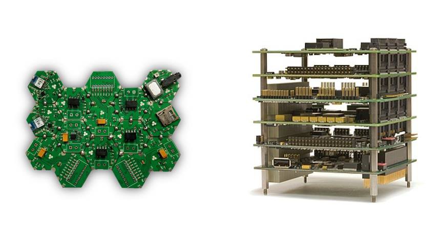
There is one basic shortcoming in many advanced electronics prototyping systems is that they are not optimized for form-factor, especially horizontal integration. This means they are not real-life-ready. Custom-made PCBs are horizontal by nature of PCB and semiconductor manufacturing techniques (traditional electroplating and lithography). By contrast, a configurable multi-module system that seeks access to same physical ports requires vertical integration. As a result, most prototyping solutions fail to produce a system that can replace custom-made PCBAs since they have a completely different form-factor.
Hexabitz emphasized horizontal integration from the beginning. This does not mean you can not do vertical integration. You can still mix both to create a complex form-factor. The only difference is that Hexabitz assembled boards (or arrays) are horizontal by nature. This makes them perfect substitute for custom-made PCBAs.
Form-factor has another dimensions to it, including volume and weight. Hexabitz mainstream implementation seeks to optimize weight and volume (and cost) as much as possible and thus eliminates connectors, wires and attachment mechanisms in favor of a simple and effective solder-based, exposed-PCB-edge connector system. Other implementations might optimize for different variables and offer different solutions.'
![]()
Figure 2. Horizontal Integration (Hexabitz) vs. Vertical Integration 3. Dual-end System for Flexibility and Scalability
In order to build a truly scalable solution, one that works for virtually all types of functionality and for arbitrary number of modules, Hexabitz is based on dual-end module architecture. The front-end is the module part (hardware and software) responsible about its unique functionality. The back-end is the module part handling all background activities including communication, addressing and other array-related functionality. The back-end, often represented by the MCU on module bottom side and the Bitz Operating System (BOS), effectively virtualizes and standardizes the interface to any type of front-end, whether it is analog signals, high-power motor, high-speed FPGA or just plain bits and pixels, they all share same interface to the Hexabitz ecosystem. The back-end resembles infrastructure in computer and communication networks, necessary to scale and standardize but not beneficial on its own. The front-end is the useful part of the process providing the end application.
The dual-end system necessitates using an MCU in every configurable module (i.e., one that can change any of its parameters as opposed to a dump battery module for example.) One might worry about cost or power consumption. The mainstream Hexabitz implementation is built around ARM Cortex-M0 MCUs, the industry-leading devices in efficiency and low-power consumption. These tiny beasts, if optimized well, are powerful enough to carry on all of the back-end (and some front-end) tasks while leaving minimal cost, weight and power consumption overhead. The massive gains in configurability and true parallel execution dwarf any overhead.
Module Anatomy
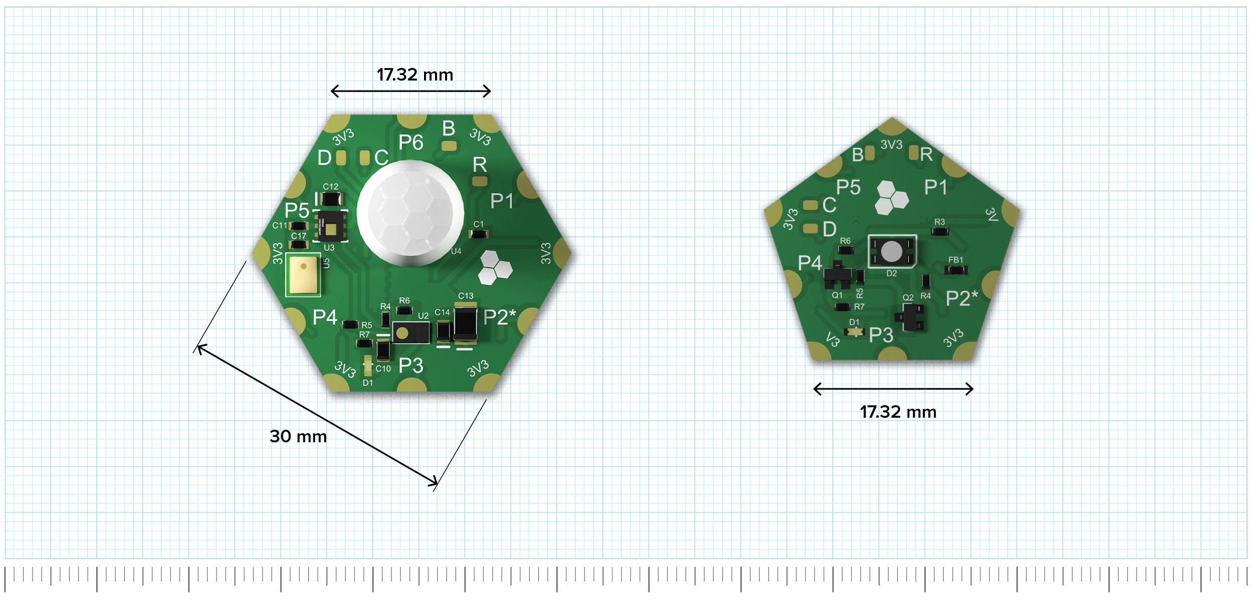
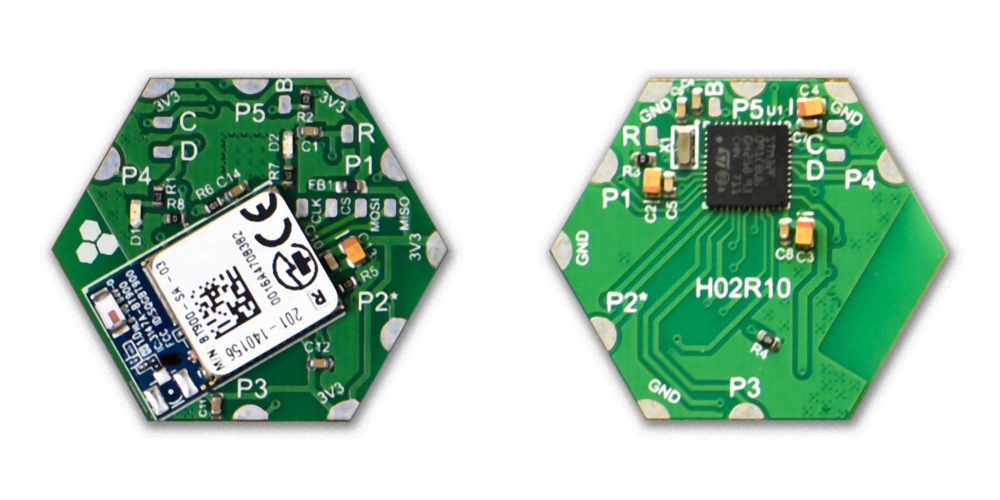
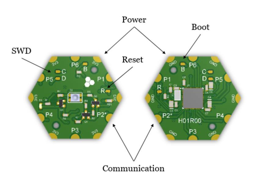
A typical configurable module (i.e., one that has an MCU) is shown in Figure 3. The top side (left) features front-end components (in this case an RGB LED) and the bottom side features the back-end hardware (i.e., the MCU).
Exposed copper areas on module corners and sides are used for physical and electrical connectivity in Hexabitz mainstream implementation. Corners are always used for power (+3.3V on top and 0V/Ground on bottom) while sides are always used for communication (TXD/transmission on top and RXD/reception on bottom). Communication ports are numbered sequentially (clockwise) starting from P1 in the module upper right corner. Some modules do not have the full set of power and communication ports due to space constraints or conflicts with other connectors. Communication ports allow serial communication (UART) between modules as well as connect the modules to the external world (e.g., cables, other boards or electronic devices). These ports can be re-purposed in many modules for other functionality (e.g., connecting input switches or different communication interfaces). Bootloader-based firmware update is also possible through communication ports. The port marked with (*) can be used with ST factory bootloader in the mainstream implementation, i.e., it allows firmware upload to an empty MCU. All Hexabitz modules back-end circuitry operates on 3.3V from the power ports. Voltages higher than 3.5V should never be applied to power or communication ports!
Another set of exposed, non-edge, copper areas (or pads) are used for non-essential connections such as programming/debugging. The MCU serial-wire debug (SWD) interface can be accessed through pads C (clock) and D (data) for programming and debugging. MCU reset pin is available on pad R and boot pin on pad B. These pads are duplicated on both module sides to allow surface connection to either side (or even though-hole connection by drilling the pad). Different Hexabitz implementations might have different set and characteristics of exposed pads.
Almost each Hexabitz module has at least one indicator LED on module top side. The general indicator LED for all modules is red-colored. It is useful to debug module status and relay various visual messages to the user. Some modules have extra indicator LEDs with different colors to convey other states (e.g., input or output power, communication, etc.)
![]()
Figure 3. Anatomy of a Configurable Module (scale 2:1) Module bottom side features, almost always, module part number while the top side has Hexabitz truncated logo on the silkscreen. Never the less, it is recommended to distinguish sides using power connectors. Top side will always have the positive voltage (~3.3V) while bottom side will always have the ground (GND).
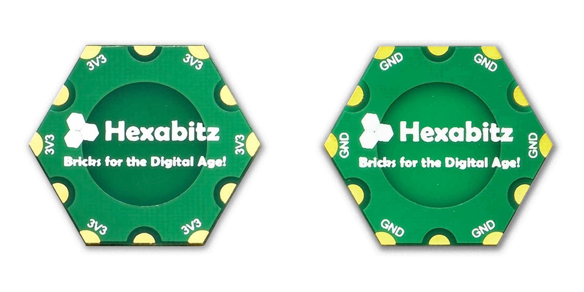
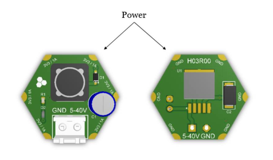
Figure 4 shows a non-configurable module. This one provides power to the array and thus features only power ports. Note that some power modules are designed to generate output voltage a bit different from 3.3V (e.g., 3V) . They can still power other modules but with possibly some functionality limitation.
![]()
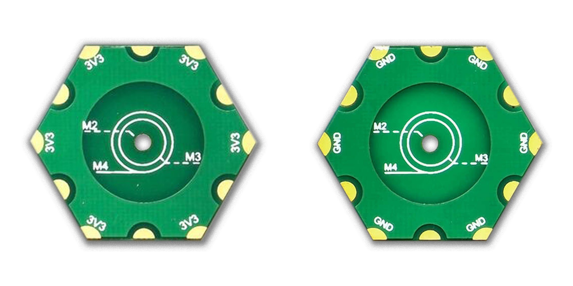
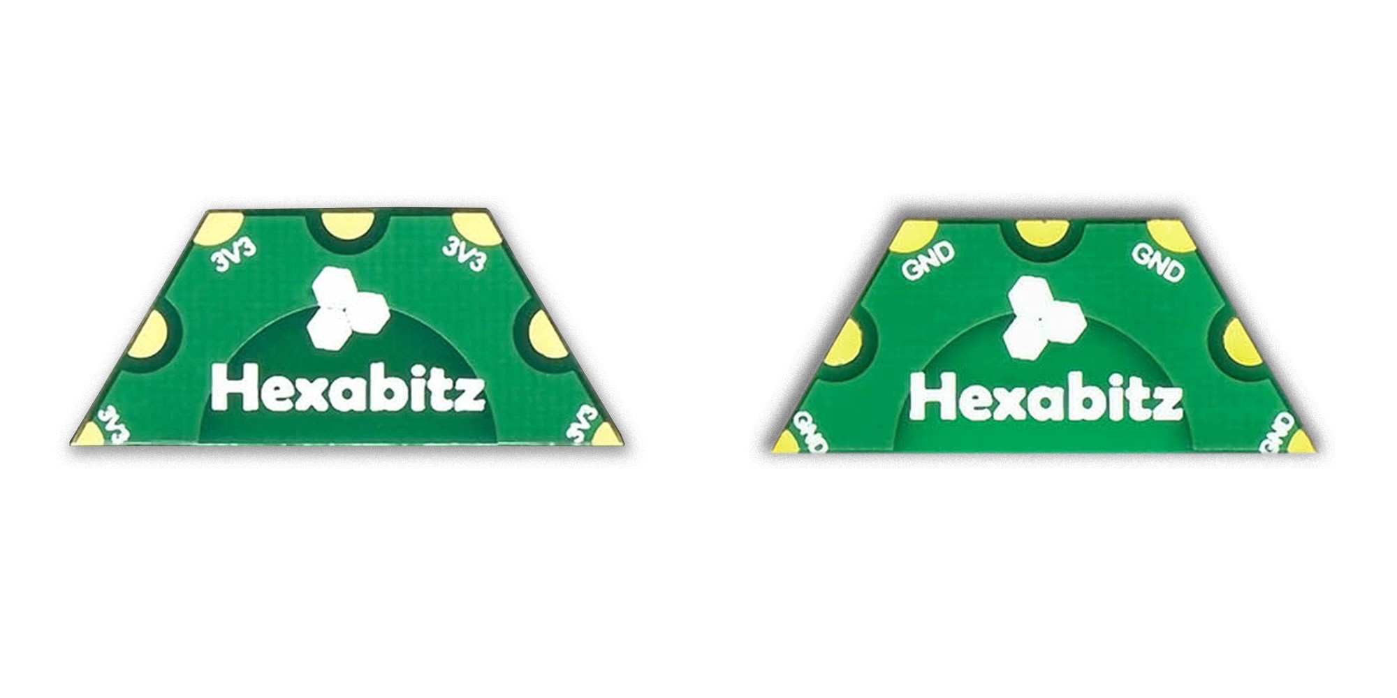
Figure 4. Anatomy of a Non-configurable Module (scale 2:1) Some modules might have mounting holes but it is not generally the case with most of them. Another special case happens when there is not enough real-state to fit the module front-end functionality (figure 5), the module will then grow in size by permanently stacking multiple geometric shapes (e.g., two stacked hexagons). This ensures the module still adheres to modularity principle and geometrical properties of Hexabitz arrays and thus can interface easily with any other modules.
![]()
Figure 5: Example of a Module with the Footprint of Two Hexagons (scale 1:1) The Array
When Hexabitz modules connect to each other, they form arrays. Arrays can have contiguous modules or ones that are kilometers away. They can be flat or curved, horizontally integrated or have a complex 3D form-factor. In theory, there is no limitation to number of modules in an array. In practice, physical limitations such as power drop and MCU memory size make it difficult to build arrays with very large number of modules. It is still possible, however, to connect as many as 100 modules together without any special interfaces. Much more than you can connect with many other platforms and in a much smaller form-factor.
Hexabitz arrays are pure peer-to-peer, mesh networks. We abandoned the conventional solution of a bus-architecture to remove any constraints related to bus topology or capacity. Hexabitz modules can connect to each other using any communication port to form any physically-possible configuration. The only assembly constraint is to make sure contiguous modules have same orientation (i.e., all facing up or down) to avoid shorting power.
Arrays are also fully distributed and decentralized systems. There is no requirement for a router or switch or main controller and thus no point of failure. The array could function in a completely decentralized way, or act as slave devices for a master module or an external controller. All depending on firmware implementation. Eventually, we hope that most of behind-the-scene work to facilitate this architecture will be carried out by the BOS to free users to focus on the end-application. All configurable Hexabitz modules are valid entry points into the array and are able to receive user commands (e.g., through BOS messages or the Command Line Interface-CLI) and process locally or forward to destination module(s).
One might be worried about latency in a peer-to-peer architecture. It is a valid concern. However, in practice, about 90% of typical applications will not suffer any latency limitation. First of all, inter-module communication is based on an optimized mix of high-speed hardware UART peripherals and direct memory access (DMA) channels. The combination of these two technologies offers a streamlined way of transferring data across the array without requiring much CPU intervention. As a result, modules can bypass communication messages with virtually no delay or CPU down-time. Hexabitz mainstream implementation can stream data across the array in speeds that can reach 1 Mbps or higher in specific configurations. Although the number might seem low for streaming applications, it is a relatively high datarate for control networks, which brings us to the next point in this discussion: Hexabitz back-end is optimized to stream control messages and not for bulk data transfers. By definition, a bunch of in-homogeneous modules (e.g., an LED, a motor drive, a BLE radio and a temperature sensor) have few things in common and will mostly need to exchange control messages occasionally. Bulk data transfers can be facilitated with other methods that break the modularity principle. Given said that, the mainstream implementation is not the only possible way to work with Hexabitz as explained in the next section. One can envision a custom implementation utilizing much faster MCUs (and even FPGAs) in the back-end if the application calls for this requirement.
Custom Implementations
Hexabitz is based on the assumption that custom electronics will always be more expensive for low quantities, take more time to make and serve only a single purpose. Although the concept itself is flexible enough to cover so many applications, one still need to make few customized decisions regarding physical implementation. I designed Hexabitz mainstream implementation to cover the requirements of majority of anticipated real-life applications. These requirements include among others:
- Full flexibility and upgradability.
- Optimized form-factor (volume and weight) to mimic custom PCBs as much as possible.
- Cost competitive solution to enable low-volume production.
- A compromise between array stiffness / reliability and assembly time.
- Robustness and reusability rate of at least 10 times during product lifetime.
Some applications, by nature, have different requirements. For example, a K12-kid-friendly application will need to replace soldering with plug-n-play connectors; a delay-intolerant application might require much faster (and more expensive) hardware for the back-end; and a safety-critical application will require even different types of components all together. Some customization might preserve components but use different solder mask color or larger (or smaller) module size or even replace the PCB with an FPC (flexible printed circuit). Still, they can all preserve same basic principles listed above. Initially, we will not target these special implementations and will focus only on the mainstream implementation (unless you have enough budget to pay for a custom set!). As time progresses, however, scale economics and network effects will make it economically feasible to offer more customized implementations.
 Hexabitz