An alternative to reducing the weight (which, given that the servos + batteries currently comprise more than half of the overall weight, and cannot be reduced) is to design the frame + legs in such a way that the servos are not supporting the weight directly. This should reduce servo wear, increase durability, and (possibly) allow the robot to carry enough weight to add a third degree of freedom to each leg.
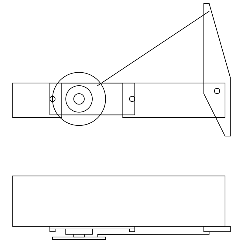
Starting out along this path, I have made the following design:

The first is the side view; the second is the top view.
The horizontal beam (femur) is to be made from aluminum L-bar, 1/16" thick * 1/2" tall * 3/4" wide. (If that is hard to imagine, think of it on end as an uppercase 'L'. One edge is longer than the other, and the thickness is a consistent 1/16").
The tibia will be longer above the joint than below. A wire will attach from the servo horn to the top of the tibia. The servo can then push / pull the tibia, using leverage to gain more torque than it could otherwise achieve (at a loss of absolute distance). The length of the tibia (or more accurately, the ratio of the length of the tibia above the joint as compared to the length of the tibia below the joint) will determine exactly how much leverage you get.
This design is simple enough that I can machine it at home without any special tools (there are really only four parts: the femur, which will have a cutout to support the servo, a simple tibia, the servo itself, and the wire connecting the servo to the tibia.
Next step is to design something similar for the coxa joint, so that the entire weight of the robot is not sitting on the micro servos. If you have any ideas on how best to do this (keeping in mind my lack of tools beyond a hacksaw and a Dremel), please comment!
 The Big One
Discussions
Become a Hackaday.io Member
Create an account to leave a comment. Already have an account? Log In.