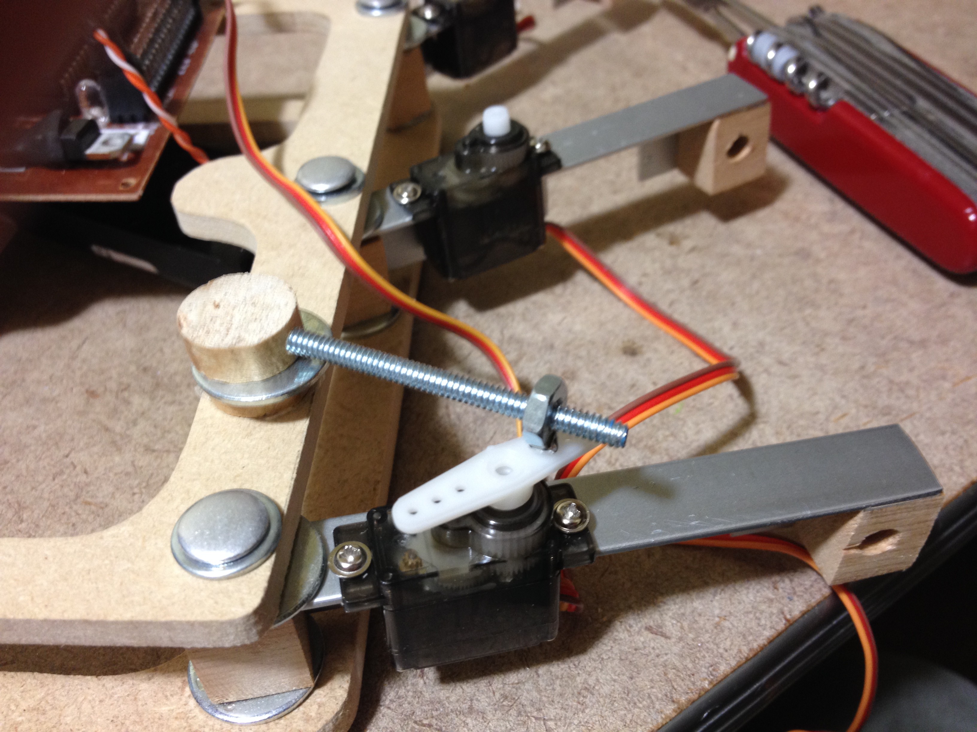
Last night my daughter and I spent some time trying to figure out the best way to make servo push rods. The goal is simple: connect the servo horn to a fixed location on the chassis, via a short rod. The length of the rod should be adjustable (to allow fine tuning of the neutral leg position), and the angle of the rod connected to both the servo horn and the chassis must be adjustable (this is how the legs actually move).
In theory this is simple, but in practice, given the material constraints which I am subject to, it is a bit more difficult.
I came up with the above prototype last night, but I didn't like it for a few reasons:
1) The center of the push rod is quite high above the servo horn, which may lead to binding, and if nothing else is inefficient.
2) The chassis-mounted portion is two slices of dowel, joined by a nail. On the bottom side, the hole for the nail is drilled out, and rotates freely. On the top, it is friction fit. In theory, this allows for free movement, but in practice it is too finicky; if the nail is too tight, it binds.
3) The entire thing looks big and bulky. While I am not making this robot for its looks, there is a difference between simplistic and elegant design vs. "throw something at the wall and see what sticks" design.
I have some more ideas to try tonight, though... here's to hoping!
 The Big One
Discussions
Become a Hackaday.io Member
Create an account to leave a comment. Already have an account? Log In.