The PCBs arrived today (1 month to the day since they were shipped... yay Hong Kong Post). I spent the last few hours soldering (and then modifying the software to use the new pins), and I now have a working board.
Pictures are below, in all their pixely goodness! Enjoy!
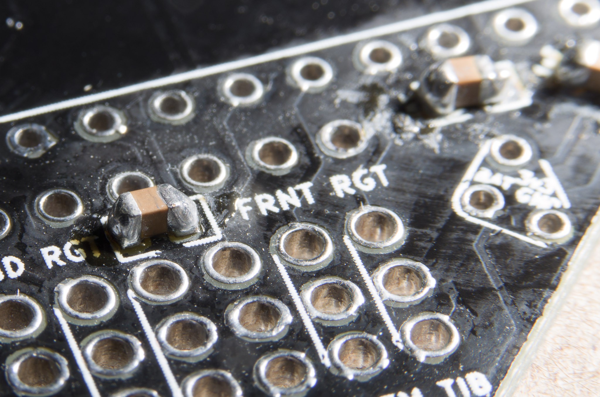
Not the best SMD soldering job, but this was my first time. Despite the ugliness, it works.
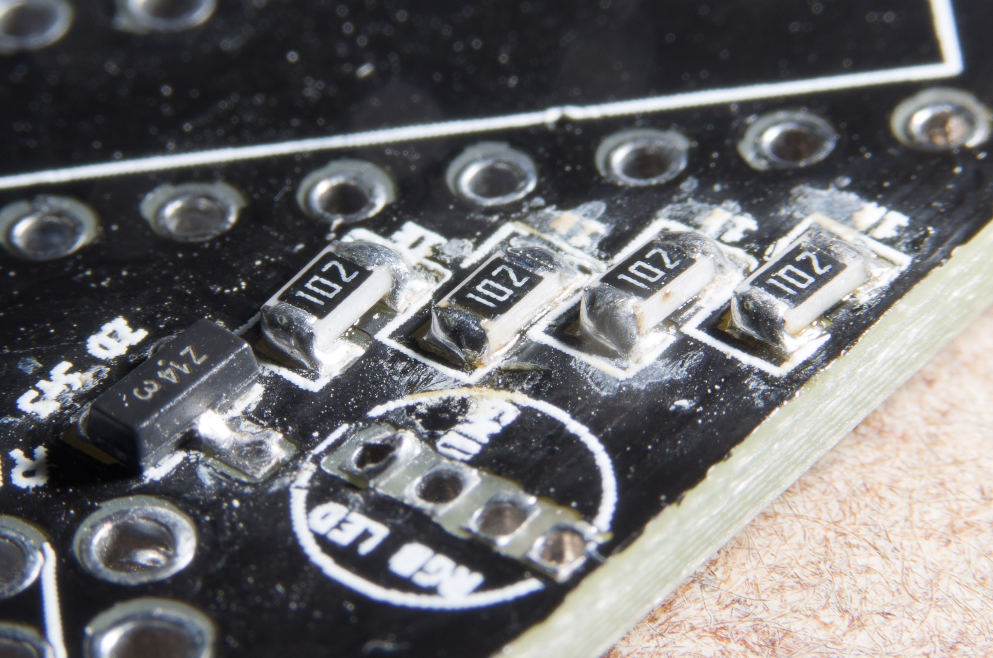
By the time I got to the RGB LED resistors, I was getting the hang of things. Still not perfect, but getting better.
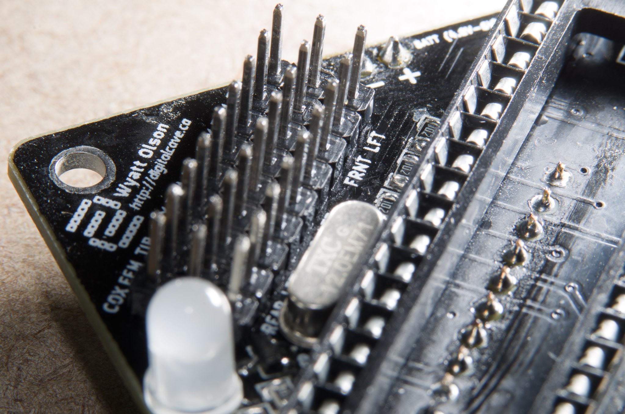
Servo pins...
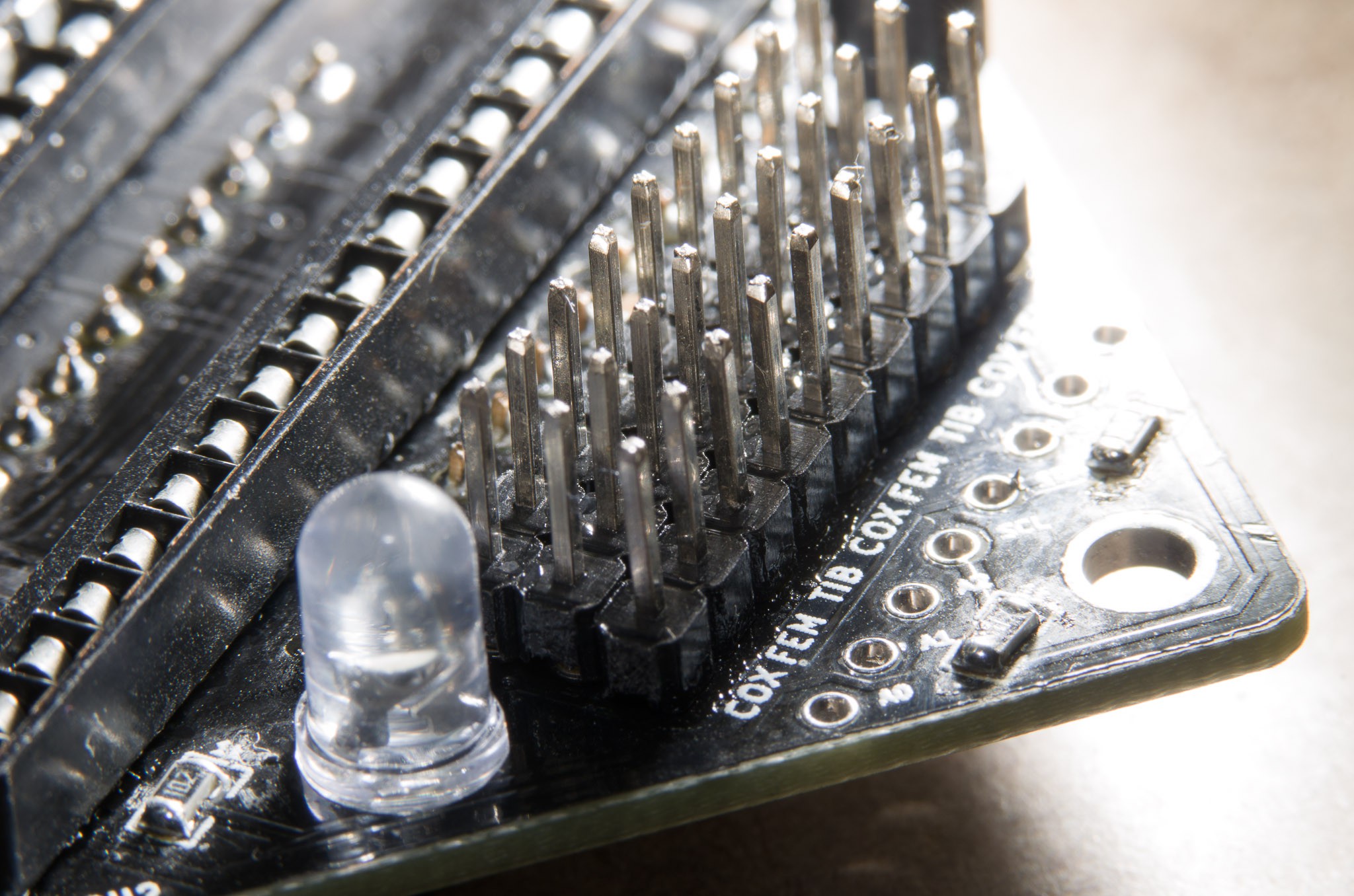
... and more...
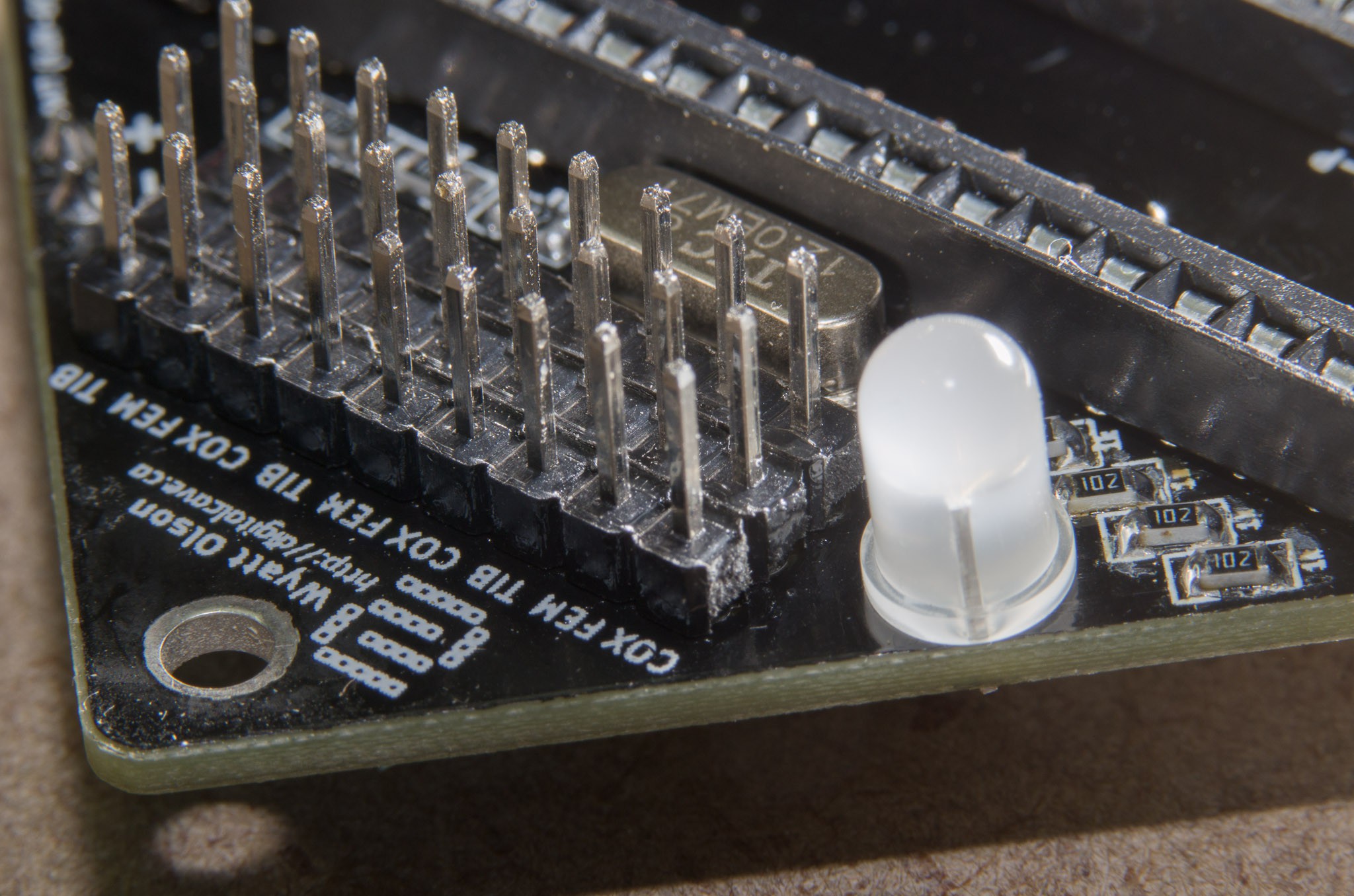
... and more....
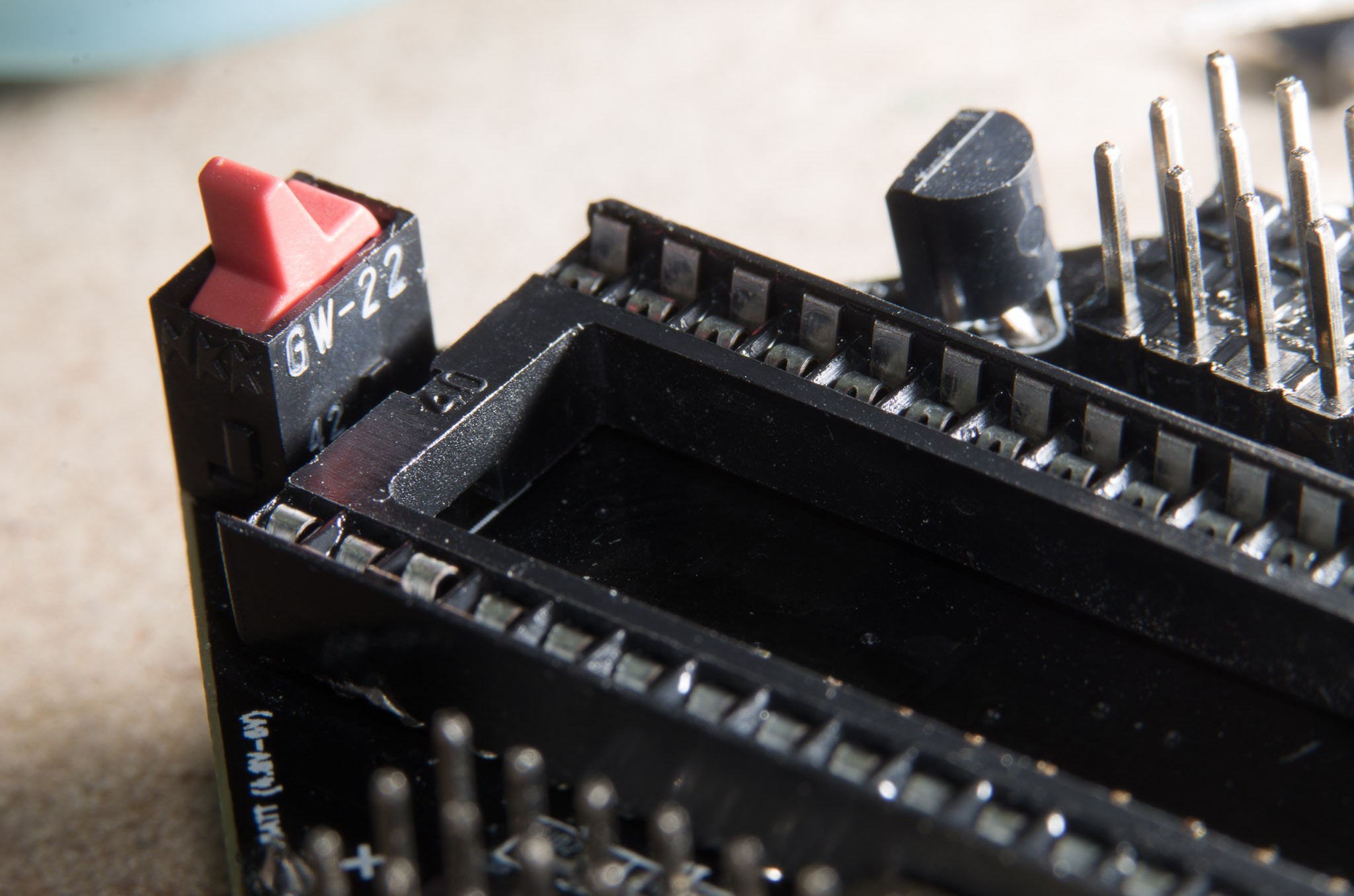
What a pretty little power switch!
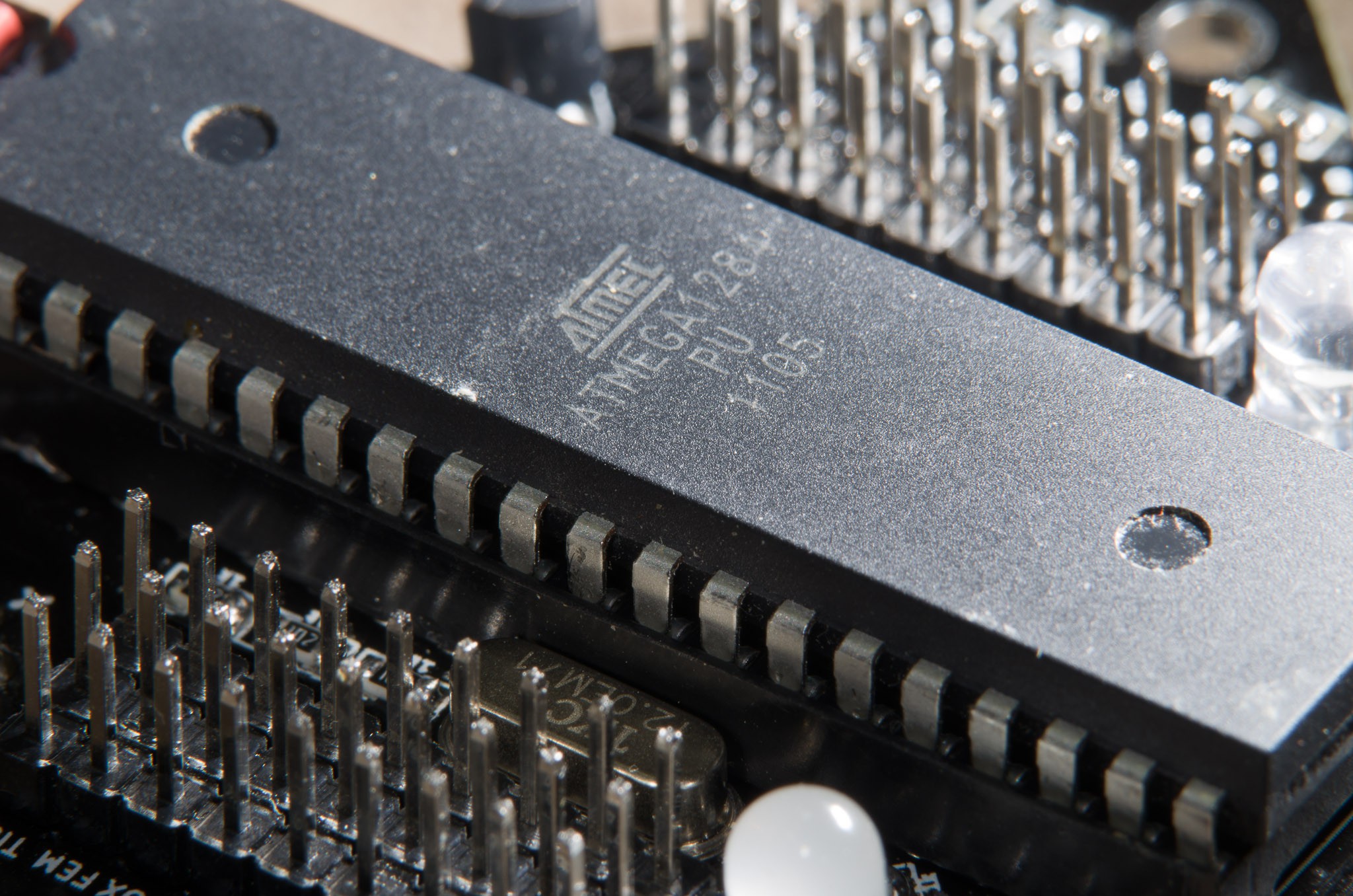
The brains of the operation
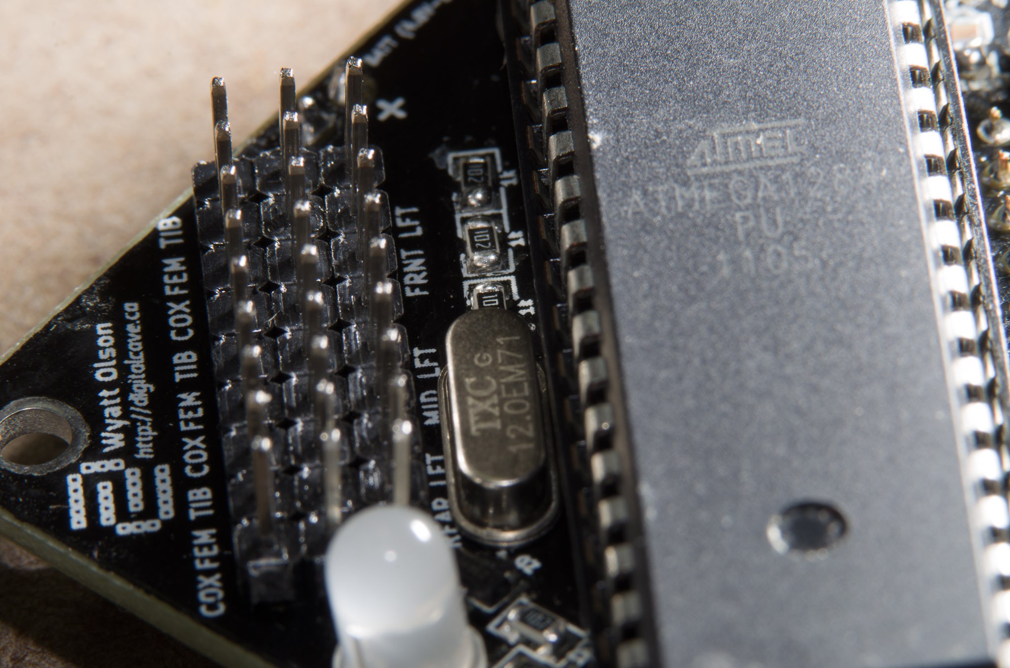
The silkscreen is not perfect (I ordered from DirtyPCBs, so I was not expecting it to be perfect), but it is more than good enough for my purposes.
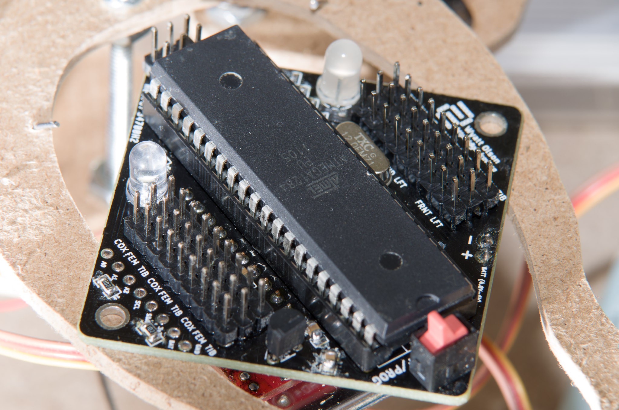
The entire board
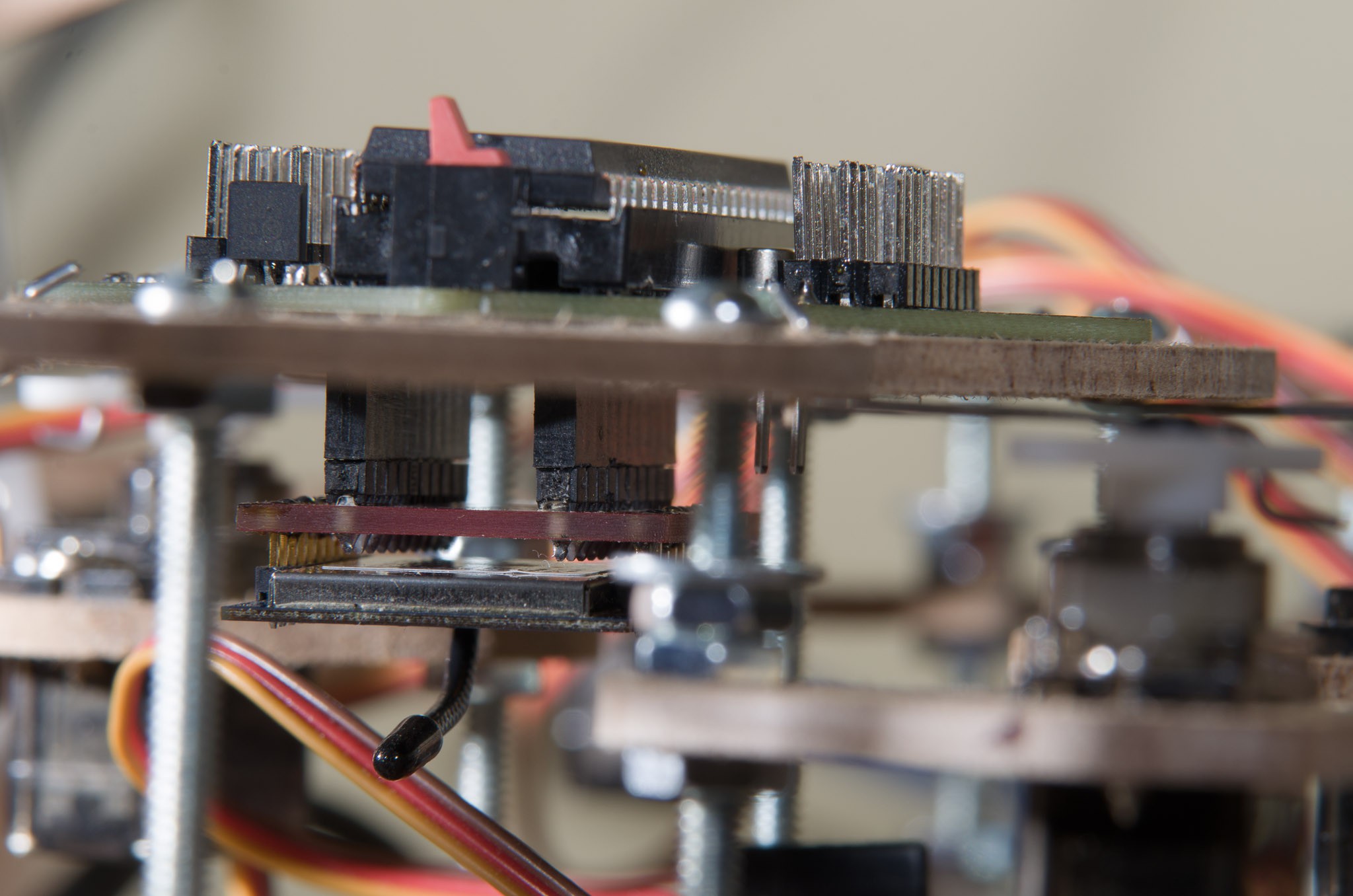
See the XBee hanging underneath. I really wish I hadn't soldered my XBee directly to the Sparkfun breakout; I would have preferred to mount the XBee directly to the headers, rather than mounting it via a breakout. I was not ready to spend an extra $25 or so to get another XBee, though. Sigh.
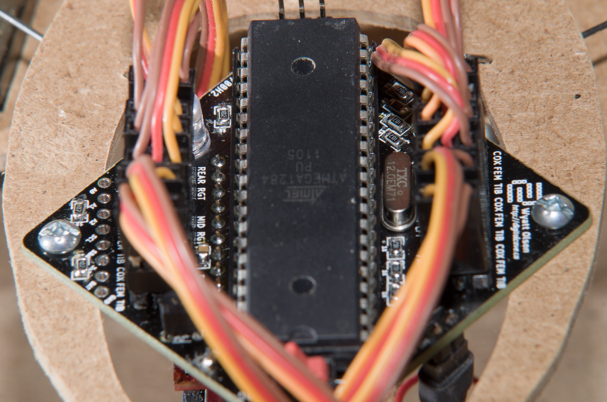
Servos plugged in
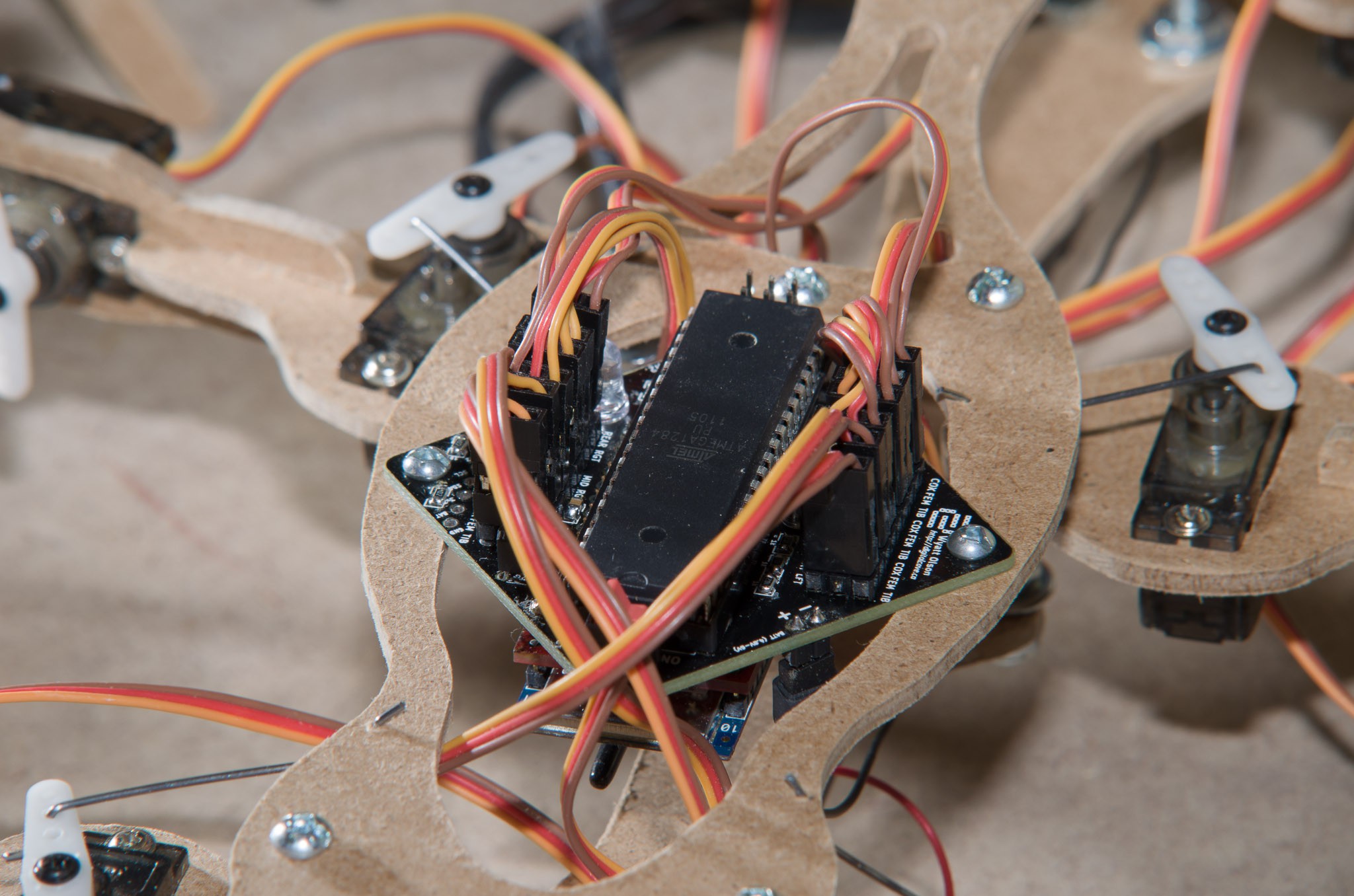
A bit of context
 The Big One
Discussions
Become a Hackaday.io Member
Create an account to leave a comment. Already have an account? Log In.
Are you sure? yes | no