Fusion 360 was used to design this boot, but the features I describe below are not particularly advanced and should be available in almost every CAD program.
I will publish files for this project, but honestly every cable is different. The first step is to model your cable so you can create a boot that conforms around the existing shape. A caliper is essential for getting accurate diameter and length measurements of your cable. I transferred these to a sketch that is revolved to create the base shape of the cable and connector.
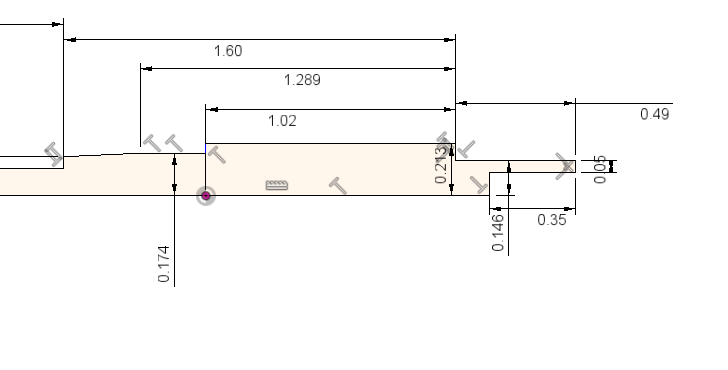

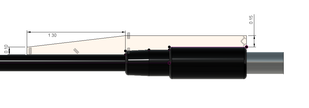
The next step is to rough out the shape of the boot, it will also be a revolve feature. I made the wall thickness about 0.15" thick. This is really beefy but it ensures the 3D print has a few layers to keep it together.

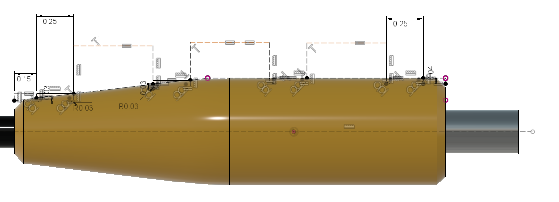
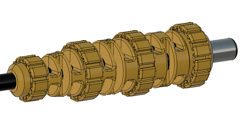
Next I added decorative fillets and chamfers and sketched the channels for the stretchy rings that will hold the boot together later. They are 0.25" wide and 0.03" deep.

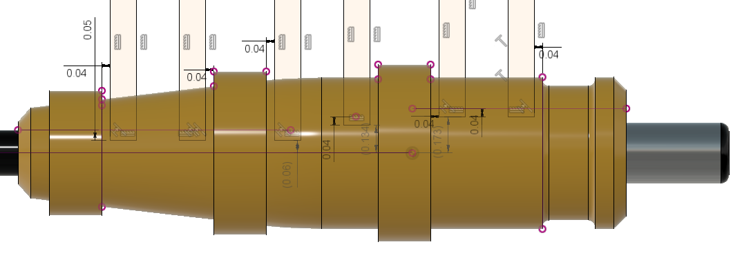
Next the basic shape for the stretchy rings are sketched so the rings can be revolved. The rings match the channel diameters and widths I created in the previous step. The rings are 0.10" thick.


Now I cut extrude some slits that will help the boot flex. The slits are mirrored and then another set of slits are made perpendicular to the first set. If you don't do this, the boot will be too rigid causing a lot of stress on the mating connector on the laptop. This is an important step.
cut:

mirror:

perpendicular sketch:
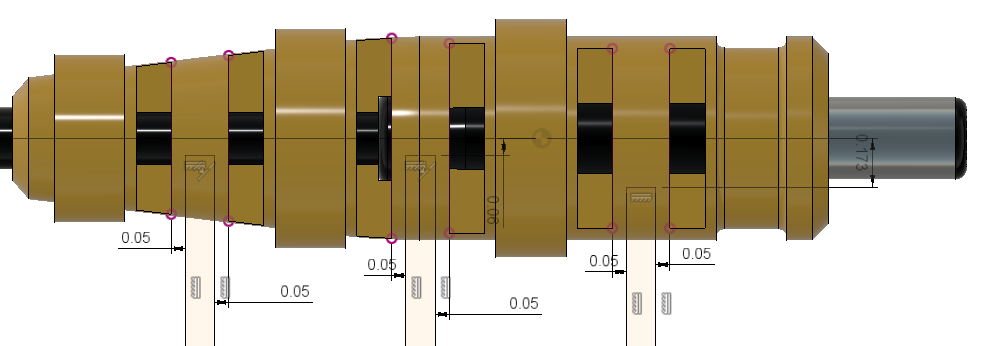
cut:

mirror:

fillet:

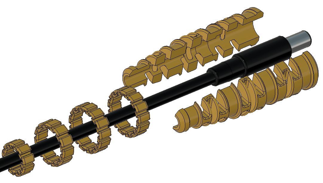
Next I created a feature called Split which is common to most CAD programs. It takes the boot and splits it into two pieces along a plane that bisects the cable.
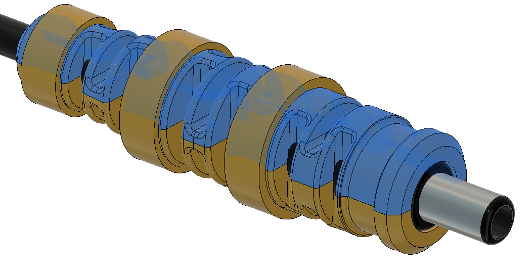
The rings need to have flexures cut in which allow them to expand. Flex filament is more flexible than PLA or ABS, but it is still very rigid and tough. This step is sort of tedious but necessary.
cut extrude an inner and outer slot:
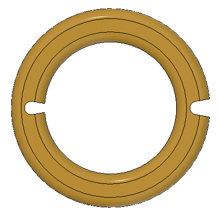
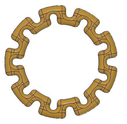
add a fillet, then circular pattern. adjust number of pattern instances until wall thickness looks consistent. These rings have a wall thickness of about 0.04" or 1mm. Repeat this process for all three rings (unless your rings are designed to all be the same, which will save a lot of time).
That's it! To install, put the rings onto the cable first, sandwich your two boot pieces around the cable, then push the rings into their respective channels. See explode view below. If you are new to printing flexible filament (which I was) - check out MatterHacker's guide to succeeding with flexible filament. The key for me was to print very slowly so the filament doesn't buckle on the path to the extrusion nozzle. Flex filament also tends to string a lot, I used a small cable clipper to cut away any strings left on the parts.
 Alex Rich
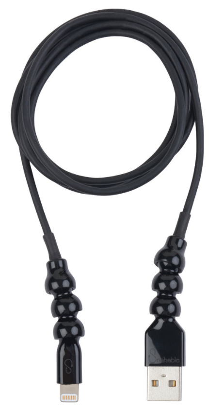
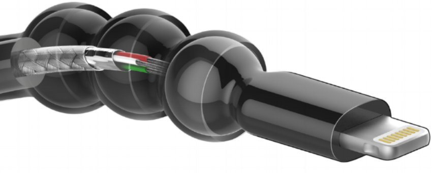



I have been looking at your piece, again, for more thn 10 minutes. It's just awesome but I think to see it everywhere we shoud simplify it! Do you think thats possible? Are you aware of the spiral strain relief design? What do you think are the pros of this design against the spiral besides that it looks super awesome and tighter?