Changelog:
2015-09-21 21:30 MDT: Added update on getting the decimal point working and a note that I soldered wires to the RTC board.
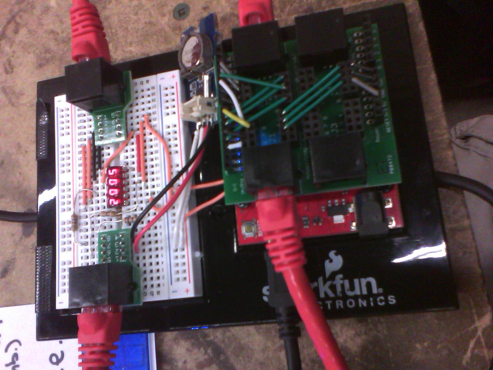
On Sunday night (September 20), I switched it from a bunch of jumper wires to actually using the Patch Shield. This made it much more presentable and durable, and the red Ethernet cables sticking way out to the sides catch people's eyes.
I also soldered some wires onto the DS1307 breakout board.

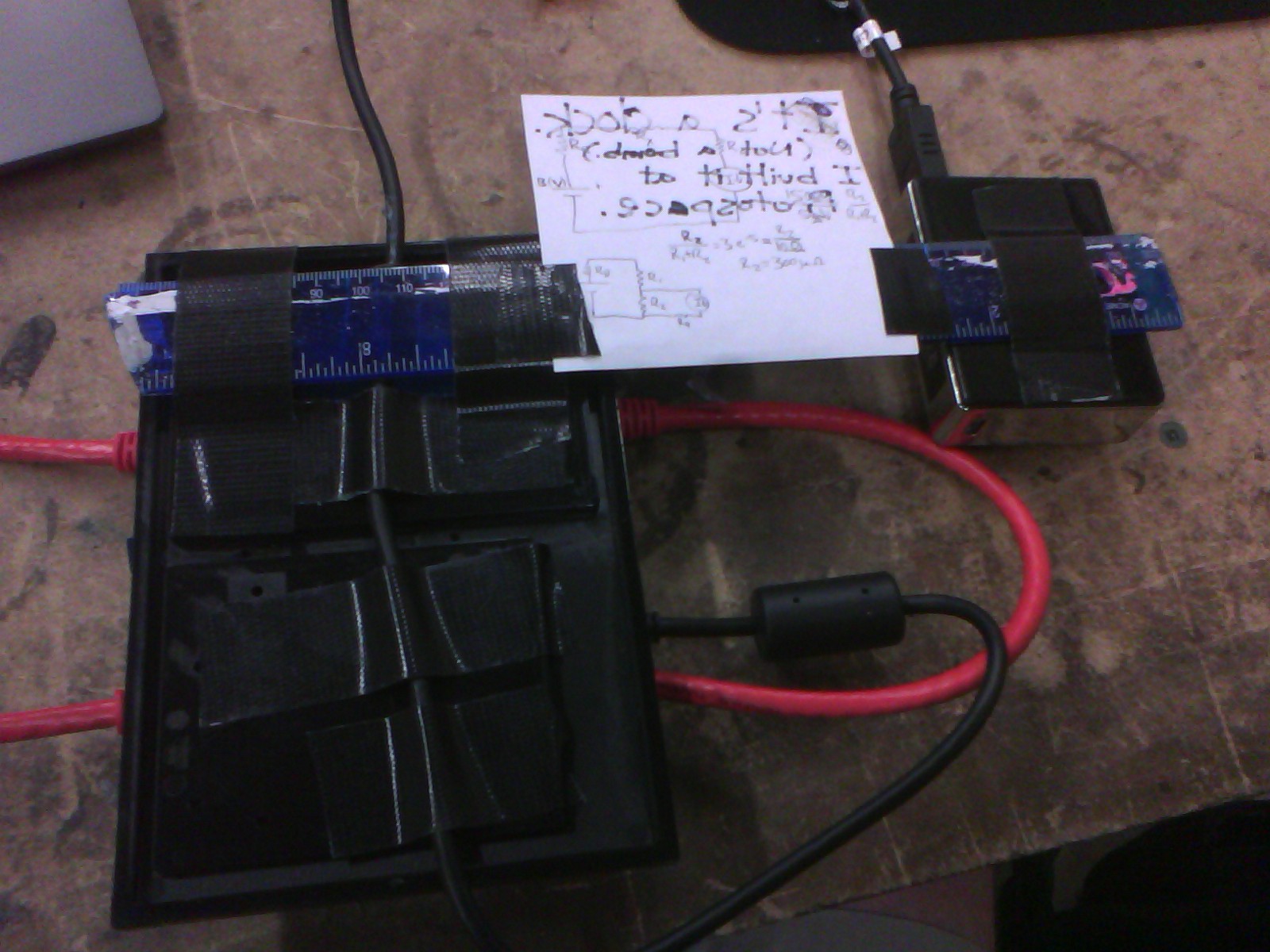
Here you can see how I built the frame with Gorilla Tape. The USB cable forms the neck lanyard; the USB battery and the clock have about the same mass. The schematics on the back of the sign were for testing a galvanometer, I think.

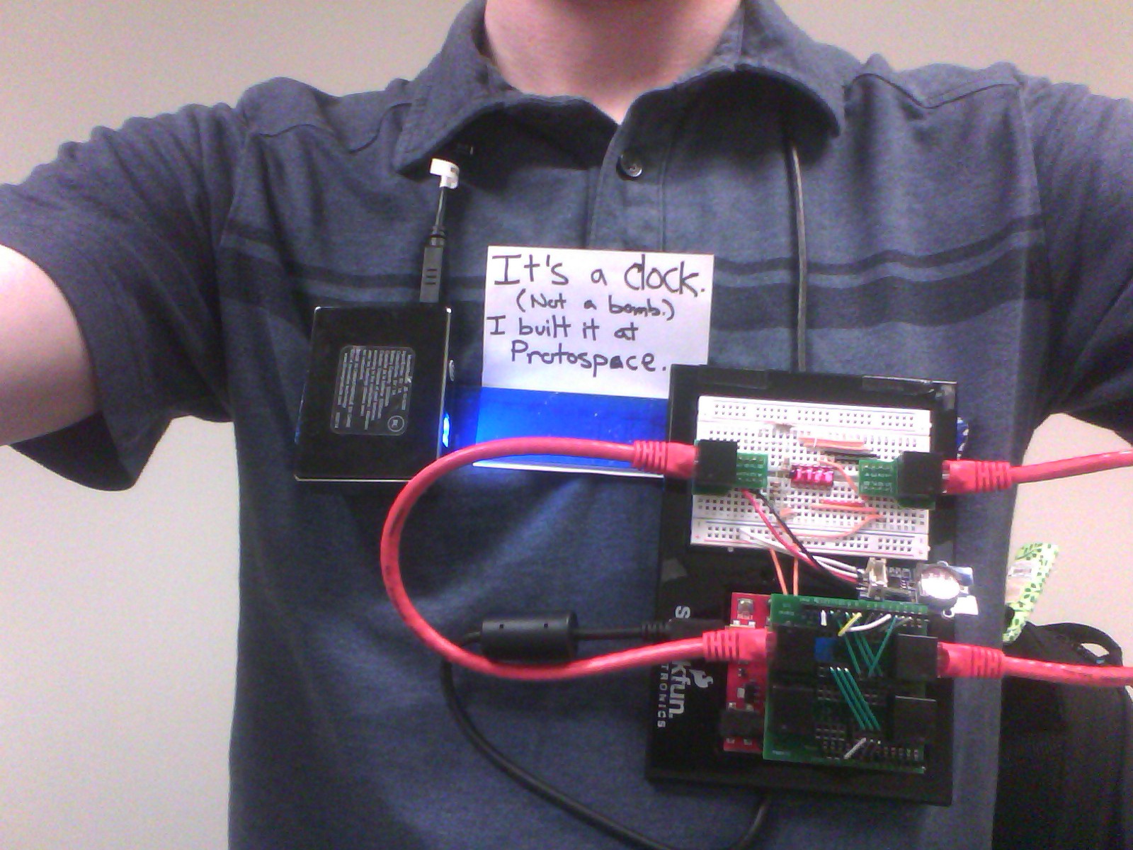
Here's how it looks being worn:

Photos still look terrible, thanks to my tablet's awful camera. (My phone is still in pieces from when I tried to repair it and had exactly as much success as Robert Liston did in his most famous surgery.) When I get home I might use a real camera, and/or one of the other hackerspace members who's a photographer/videographer wants to take a picture of me wearing it, so better photos might be coming soon.
To Do:
- The bubble displays have decimal points, but the sketch I'm running currently doesn't have them enabled. I'll probably have that fixed tonight.
Update: Fixed! It was a simple matter of adding a pin to the display definition (using the SevSeg library), as I expected. Now it displays HH.MM as desired. It would be nice to have a colon instead, but I'm not too bothered (though I'm slightly bothered that the decimal point is substantially below the digits). While looking for power resistors, I found we have a bunch of ancient red LED 7-segment displays (probably the ones that replaced bubble displays in products), some of which have colons, so maybe I'll use those in a future version. - I need to trick the USB battery into running continuously. It turns off after several seconds due to too little current draw (because it's designed to charge smartphones). I need to figure out how much current it needs drawn to stay on, and how frequently this current must be drawn (which I'll then program the Arduino to do with the help of a transistor and resistor). Unfortunately, this hackerspace seems to lack any kind of dummy load. Even just bare power resistors we don't have much selection of.
- For miniaturization, I need to get some kind of softRTC running so that I can run it on a bare LiPo battery instead of the USB battery (which is a giant LiPo battery with a built-in 5 V boost converter). (The DS1307 requires 5 V.) I tried RTClib's softRTC, but I found it too difficult to use. (Or maybe I just wasn't reading it right; does anybody have experience with it?) So I wrote my own super-simple, 12-hour, non-sleeping softRTC implementation. That worked but when I added interrupts for buttons to increment the hour and minute, both incremented at 60 Hz even with no buttons connected. I think this might be mains noise. A multimeter only picked up about 0.12 V AC on the inputs, but there could be more when the meter isn't loading it down. I'll have to look into how other ATmega328p-based watches do it. This will also be applicable to my Word Watch project. More on this in a future project log post.
 PointyOintment
Discussions
Become a Hackaday.io Member
Create an account to leave a comment. Already have an account? Log In.