To make the experience fit your profile, pick a username and tell us what interests you.
We found and based on your interests.
I guess I did it again. Between work, moving into a new apartment, and the holidays, I let this go again. But it's update time.
Let's talk about the MAX6920. The only one Mouser has listed is the MAX6920AWP+, which is probably the one I used, but I bought these some years ago, so I'm not entirely sure. Current price is 4.33 USD, so they're quite pricey compared to the other components. The fact that they're SOIC-20 (eep!) means that you're probably going to want to get a few of them, because they're tricky little guys who solder down. I'm not great at soldering, but I was able to get the process nailed down after frying one of them.
Datasheet is at https://datasheets.maximintegrated.com/en/ds/MAX6920.pdf.
Pins:
1. VBB. VFD Tube Supply Voltage. 8-76V.
2. DOUT. Serial-Clock output. This is used for multiplexing another shift register and won't be used for our project.
3-8, 13-18. OUT0 to OUT 11. VFD anode and grid drivers. Push-pull between VBB and GND.
9. BLANK. Forces output pins low when voltage goes high.
10. GND. Ground.
11. CLK. Serial Clock Input.
12. LOAD. Load input. This loads values into your shift register
19. DIN. Serial-Data input.
20. VCC. Logic supply voltage.
That's a lot of pins. To make matters worse, the datasheet describes the function of the pins like an electrical engineer would expect them to be, not a scrappy developer out of his element. VCC is just logic voltage. Nothing exciting there. Give it a 3.3V or 5V from the arduino and let's move on. GND is ground. That's easy enough too. VBB is tube supply. That's what we want getting passed over to the grid and filament pins on the VFD, and the OUT pins is how we get them there. So we'll wire the OUT pins to the filament/grid pins and wire the output of the NCP1403 to VBB. BLANK has behavior for high and low. There's no expected behavior for it being left floating, and we want output right now, so lets ground that out, and consider uses for it later. We're not going to use DOUT, and it looks like we can leave it floating, so that's fine. Now DIN, LOAD, and CLK. Uh, well, they'll need to be wired to digital arduino pins so we can write to them. Hmm...
That's okay though, lets look at the following process carefully (datasheet, page 7):
The MAX6920 is written using the following sequence:
1) Take CLK low.
2) Clock 12 bits of data in order D11 first to D0 last into DIN, observing the data setup and hold times.
3) Load the 12 output latches with a falling edge on LOAD. LOAD may be high or low during a transmission. If LOAD is high, then the data shifted into the shift register at DIN appears at the OUT0 to OUT11 outputs. CLK and DIN may be used to transmit data to other peripherals. Activity on CLK always shifts data into the MAX6920’s shift register. However, the MAX6920 only updates its output latch on the rising edge of LOAD, and the last 12 bits of data are loaded. Therefore, multiple devices can share CLK and DIN as long as they have unique LOAD controls.
This is further augmented by figure 3 on page 6. So let's try to turn this, between the two, into something more arduino friendly.
1. Set CLK low
2. Set DIN high or low as appropriate for D11.
3. Set CLK high.
4. Repeat Steps 1-3 until having worked from D11 to D0.
5. Set CLK low
6. Set LOAD high, then low to "load" the logic into the registers.
Well, that helps, but it's still cumbersome. Let's actually turn it into code.
Our constants:
// change these if your arduino pins are wired
#define loadPin 8
#define clkPin  7
#define dinPin  12
// these are shift register pins I've selected.  Change them if you're using different ones.
#define grid1 7
#define grid2 8
#define grid3 9
#define grid4 10
#define grid5 11
In setup(), we'll need to define outputs:
  pinMode(dinPin, OUTPUT);
  pinMode(clkPin, OUTPUT);
  pinMode(loadPin, OUTPUT);
Now lets make this process simple through a function:
void writeToShift(int segment[], int grid)Read more »
{
for (int i = 11; i >=0; i--)
{
bool writeNum = false;
for (int j = 0; j <= 6; j++)
{
if (i == segment[j])
{
writeNum = true;
break;...
So, I kinda let this fall by the wayside (again), but I'm going to try not to do that YET again.
Here we go:
The NCP1403. It's a step-up DC-DC converter in a tiny surface mount package produced by ON Semi. The datasheet is available at http://www.onsemi.com/pub_link/Collateral/NCP1403-D.PDF.
This is where things start to get complicated, but lets start with the pinout.
Tolerance on the VDD is -0.3V to 6.0V, so I should be good for mobile applications (probably going to be 3.4V) as well as something powered by mains (probably 5.5V). Thats good. I set CE to a pin on the Arduino. That means a little more power draw, but that will allow me to do things down the road like put the screen to sleep. Overall it should save more power than it uses, and if it doesn't, well, nothing solves that problem like an xacto knife across the trace on the board.
We need to find the voltage for our feedback resistors so that we can set our voltage. The equation is:
Err... well then. I know what I have laying around my apartment, and I know what I need for an output voltage, so I guess let's plug some numbers in and see what we get.
I know I need at least 10V. So we'll start with Vout = 10, and then figure the closest values to real capacitors I have otherwise. Expressing the formula another way:
So increasing the overall voltage is dependent on increasing the value of Rfb1. Tossing values in there for resistors (I'm writing the book so I can read ahead anytime I want :) ) with Rfb1 = 1M and Rfb2 = 82.8k, V = 10.46. That actually comes out being closer to 10.35 in real life, because life isn't ideal. But so it goes, and so do we, onto talking about the circuit design.
There's a lot of ways you can put this SOIC to use. The one I'm going to use is straight out of the datasheets. Page 2, Figure 1. Other than the resistors we hammered out earlier, use values as close to what is recommended as possible. You want the 47uH inductor and the MBR0520LT1G diode, as it's the current revision. From what I can tell, it's somewhat of a specialty diode, and as far as I know it only comes in the SOIC package, but it's pretty cheap. Mouser currently lists them at 0.32USD per unit.
One last note, they don't outright list a recommended capacitor for Cc in that diagram anywhere that I noticed, though they recommend a disc capacitor. I used a 10 nF one. I get some voltage flux within about a volt or so, but I haven't noticed any real flicker or anything, so I'm calling it close enough for my hack. I imagine that if I were someone who actually knows what they're doing, I'd probably start tweaking things there to get more consistent voltage.
I'm going to start talking about the MAX6920 shift register in the next update. It's wired up, so I'll start writing that up tonight but we'll see if I finish it in time to post. I imagine that I will need to start talking code at that point as well.
To set the scope of what I am and am not going to talk about here:
Now that I've gone through that, this thing took me far longer than it should have to figure out, partly because I'm not an engineer, and partly because documentation for this thing is dodgy at best. Having that been said, it has a clear backing and all the traces inside are visible, so it's not hard to puzzle through. Lets look:

The thing that surprises me is that an easy 50% of the pictures out there have the thing pictured upside down according to the data sheet (handy information providedhere). One side of the VFD has 16 pins on it, and the other side has 7(!) but you don't actually need those 7. You can use them, or you can cut them off. What, you say?! Well, those 7 are actually duplicates of some of the ones on the opposite. Technically, this doesn't matter, as if you design your build from the upside down perspective, it works perfectly still, but when talking about the pins, it's important to keep a common perspective, and this is the one I'll be using.
The bottom pins are the ones I'll be talking about, because they're the ones I use. Numbered, from left to right, they are:
The top pins are duplicates of the filament and grid pins. Using them might make sense, or it might not. If you want to use them, just look through the VFD to see which grids they correspond to. They're not too hard to trace.
Next, we'll start with making it do something. To start, you need current passing through the filament to get any reaction. I use 3.3V because it's conveniently offered by the Arduino and also within range for VCC for everything else I have attached. It's a little hot for the filament, and you'll see a slight red glow from it, but I don't think it's enough to cause any real lasting harm. Don't go higher than this. Note that 3.3V may shorten the life of your VFD though, so if you feel up to it, check out a calculator for a voltage divider and reduce it to something lower. It's rated for 2.4V, but I think you could go as low as 1.2V and still get output, though I haven't tried it myself. The grids and the segments both use the same voltage (24V), which is convenient to us. You can also drive them at a much lower voltage, though I suspect that they'll be dimmer as a result. I use about 14V myself and still get enough glow to comfortably read in anything except maybe direct sunlight. Overall, what this means is that you can make this work off of two voltage rails, a 1.2V-3.3V rail (I'll call this 'low voltage') and 14V-24V rail (I'll call this 'high voltage'), and a common ground.
So at a minimum, you should be able to light up a segment by connecting:
If you want to make sure your entire VFD is working properly, connect pin 1 and 16 as above, and everything else to high voltage. If it doesn't light up with '88:88', then something's gone wrong. Check voltages, make sure you're delivering enough current (an Arduino Uno should be able to handle this), and then try another VFD. One of mine was shot, and I spent more time troubleshooting that than I should have. Most vendors for these seem to sell them in sets, so I'm sure you have another one.
An observant person at this point would exclaim, "But wait! I can't get just one digit to light up! If I power all the grids, all the segments light up." Yup. You have to cycle through each grid with the right configuration...
Read more »I haven't updated this... like, at all. I started some writeups on my personal website. I'll repost them here to try to catch up, and attempt to get myself to finally find time to finish this.
One of the coolest things I've seen in a long time is johngineer's ChronodeVFD project. Unfortunately, he doesn't provide schematics or a lot of details about his project beyond a high level description of some of his design considerations. He does mention some of the core components he used though:
The datasheet for the NCP1403 recommends a particular diode (MBR0520LT1) for use with the step up circuit, so I got a couple of those also.
Note that most of those components above are surface mount form factors. The MAX6920 is a 20 pin (!) SOIC, so if you're not comfortable with that level of precision in soldering, it might be best to look for some larger form factor. Being a masochist, I got the SOICs.
I suppose before I get started I should declare that my intention isn't to replicate the same wristwatch that he created, but to use similar components to come to the same end functionality. For now, I'm going to use an arduino uno instead of the ATMega88, and rely on a wall wort rather than work in battery power. I'm also going to try to go as simple as possible. KISS policy in effect here. I'm also learning as I go, and I'm not exactly an electrical engineer, more like a clever idiot.
So the first thing that needs to be done is to prove that the VFDs even work. I mean, they're Soviet surplus that's just been sitting god knows where for the last 20+ years, so who knows? I got a pack of 10 from my friendly Russian ebay dealer. They arrived, box covered in customs stamps with the inside stuffed with Russian newspaper. If I wasn't on someone's watch list before, I'm sure I am now. :D
In order to be able to get any sort of reaction from the VFD, you need some different voltages. The datasheets call for a filament voltage of 2.4V, a grid voltage of 24v, and an anode voltage of 24v. You don't want to exceed them by much, but you can actually drive it at lower voltages fairly nicely. I got a pretty good reaction from 3.3V (hot off the Uno) on the filament, and set up the NCP1403 to output @ 15.5V for the grid/filament:

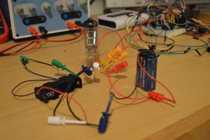
What you see here is 3.3v on pin 1 of the breadboard, 15.5v on pins 2-15 (provided by the voltage converter on the right side) and then ground is awkwardly alligator clipped to the top of the VFD (the pins are fragile and I mangled the filament pin on the bottom while trying to plug it into the board). That should be enough to get you a lit up display and confirm that yours works!
I'll be going into the pins on the VFD in further detail, along with talking about the voltage converter in the next post.
Create an account to leave a comment. Already have an account? Log In.
Well, I had the MAX6920 post about 90% done, but then I closed the wrong window and now it's gone forever. So that's not happening tonight. I'll see if I can get that done sometime soon.
Become a member to follow this project and never miss any updates

 w_k_fay
 Karl S
 John Duffy
 Matthew Peverill
I'm certainly a little lost and I couldn't find the complete sketch; then, please! Thanks