The design of the printer revolved around 3 layers of lasercut MDF. which in turn are bolted to 3 vertical lengths of openbuilds 2020 extrusion, for linear motion and a sturdy frame.
In order to securely attach the lasercut plywood to the extrusion I designed a simple bracket.
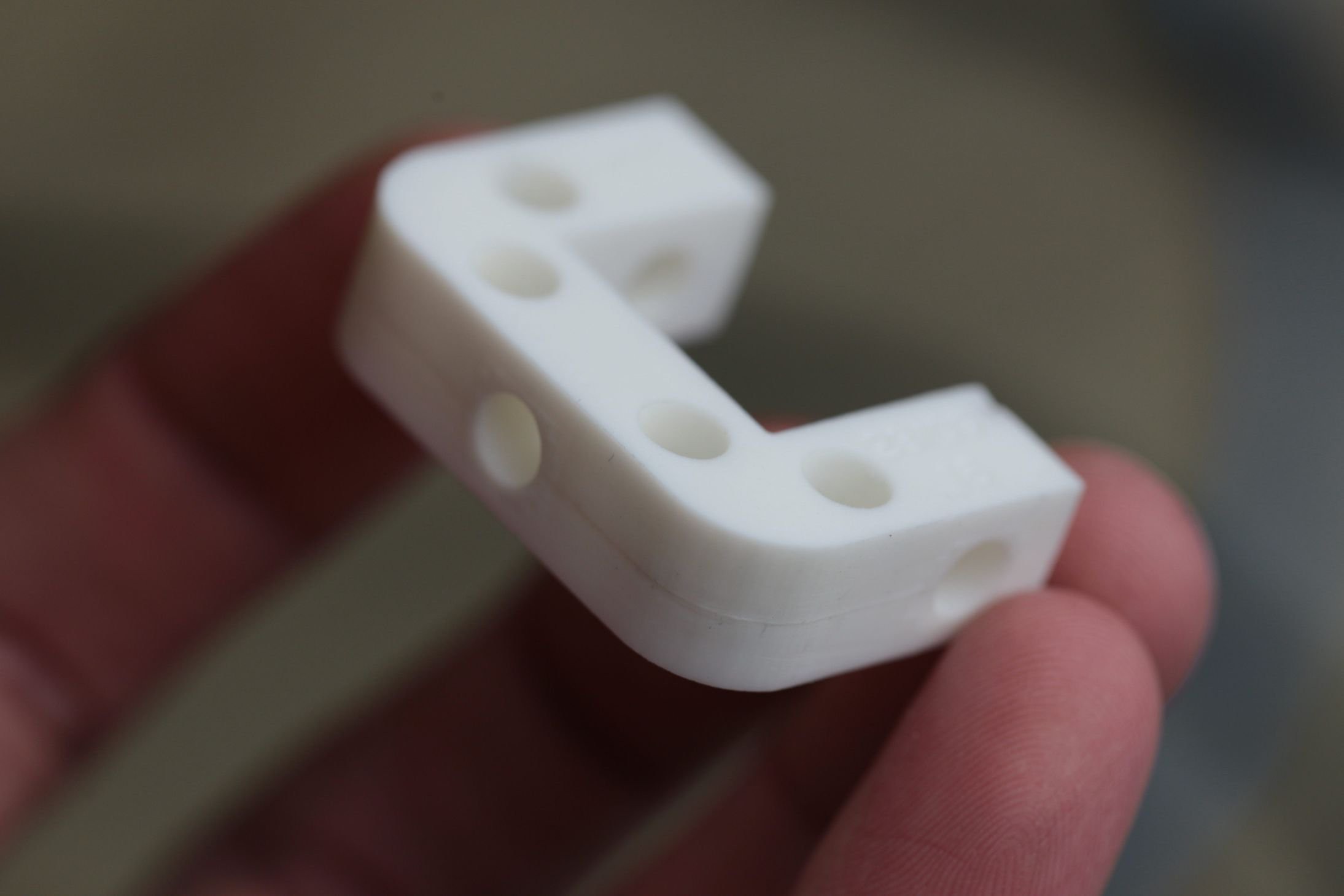
As you can see it has 4 holes that match with the horizontal plane of the MDF. Then 3 holes around the central extrusion allow it to be bolted solid. Due to the complex geometry of this part it cannot be made in a single mold.
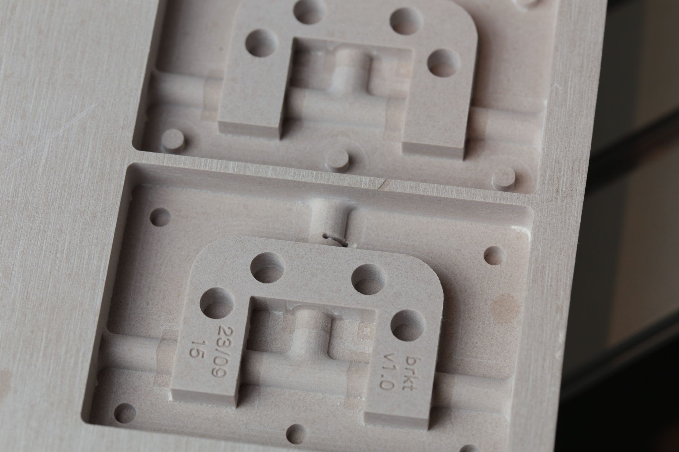
My solution to this was to create a two part mold. And utilize rod stock during the casting process to form the horizontal holes.
You can see the difference in surface apperance from the 3.2mm rough pass and the 1mm cleanup pass. I am still perfecting good tool paths.
On the topic of good tool paths I made a blunder, and when re-zeroing my Z axis after a tool change entered the wrong value. The astute eye can easily notice the location this break occured in the above shot. I did not re-do the mod as this blemish can be easily removed from the silicone mold.
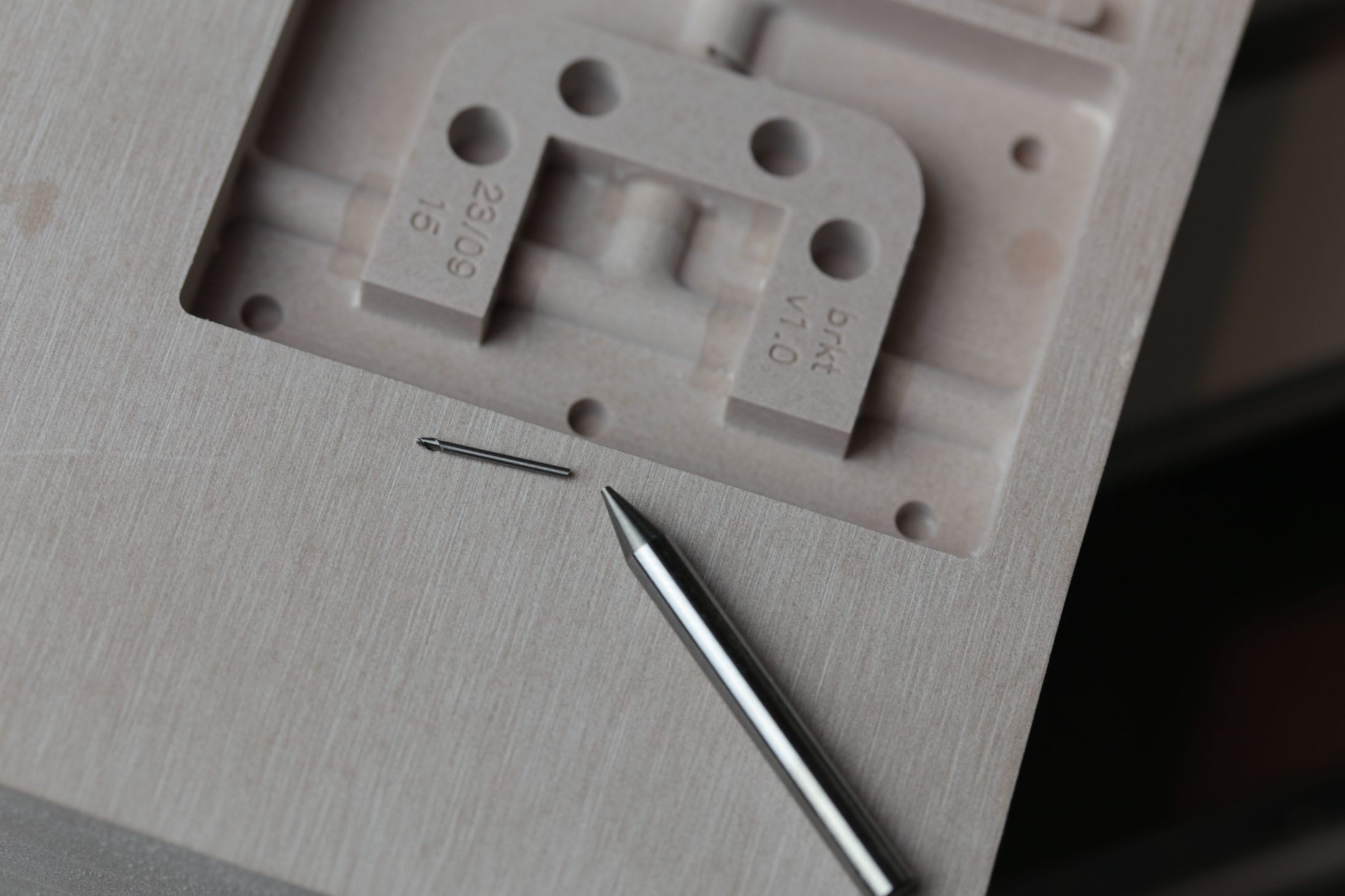
A $20 +p/h mistake, I have always kept 2 tools of each size on hand, so my work wasn't stalled. I have promptly ordered a new one. (They're not stock items at my local machinist store, so they need to be ordered in)
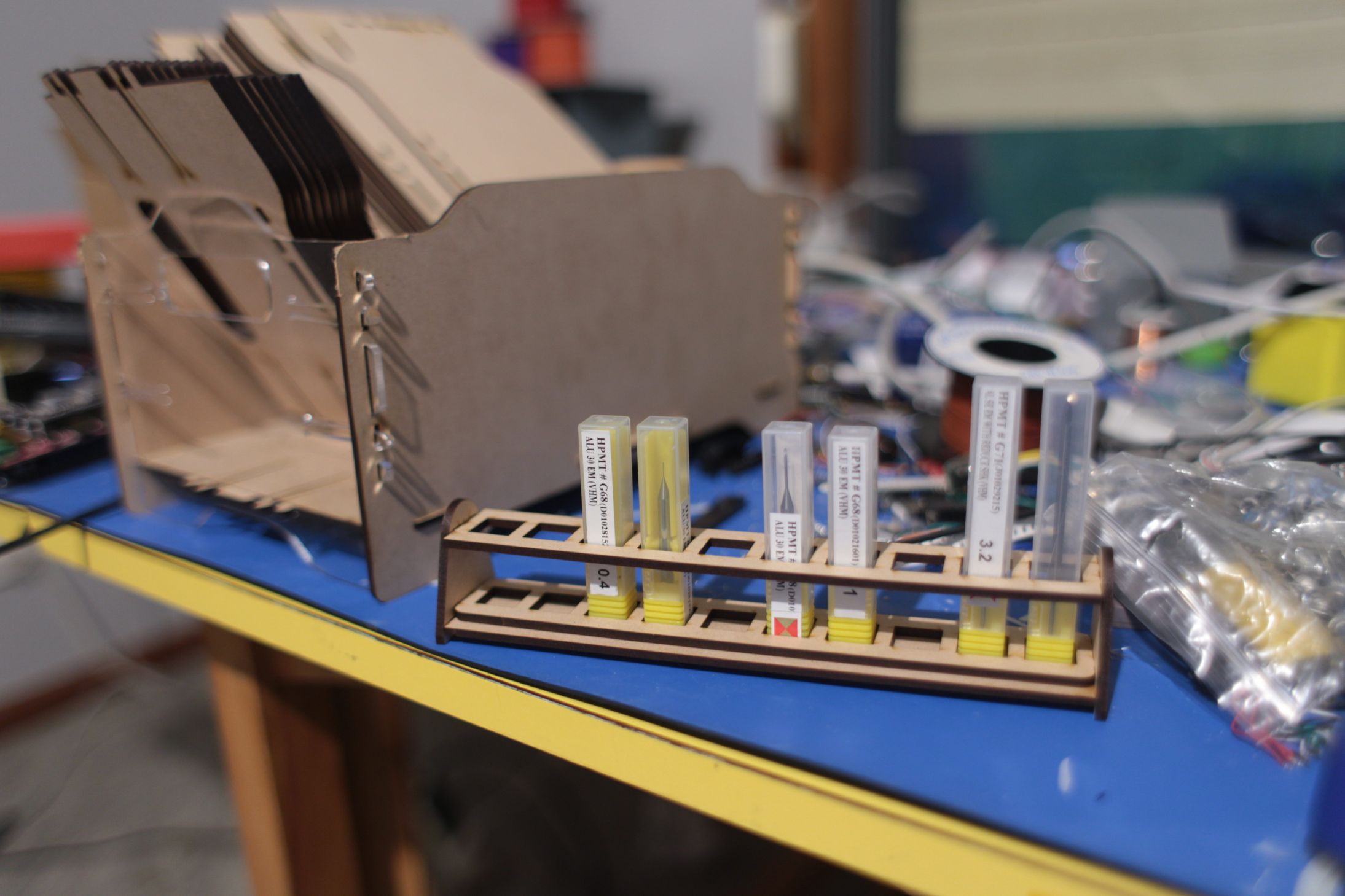
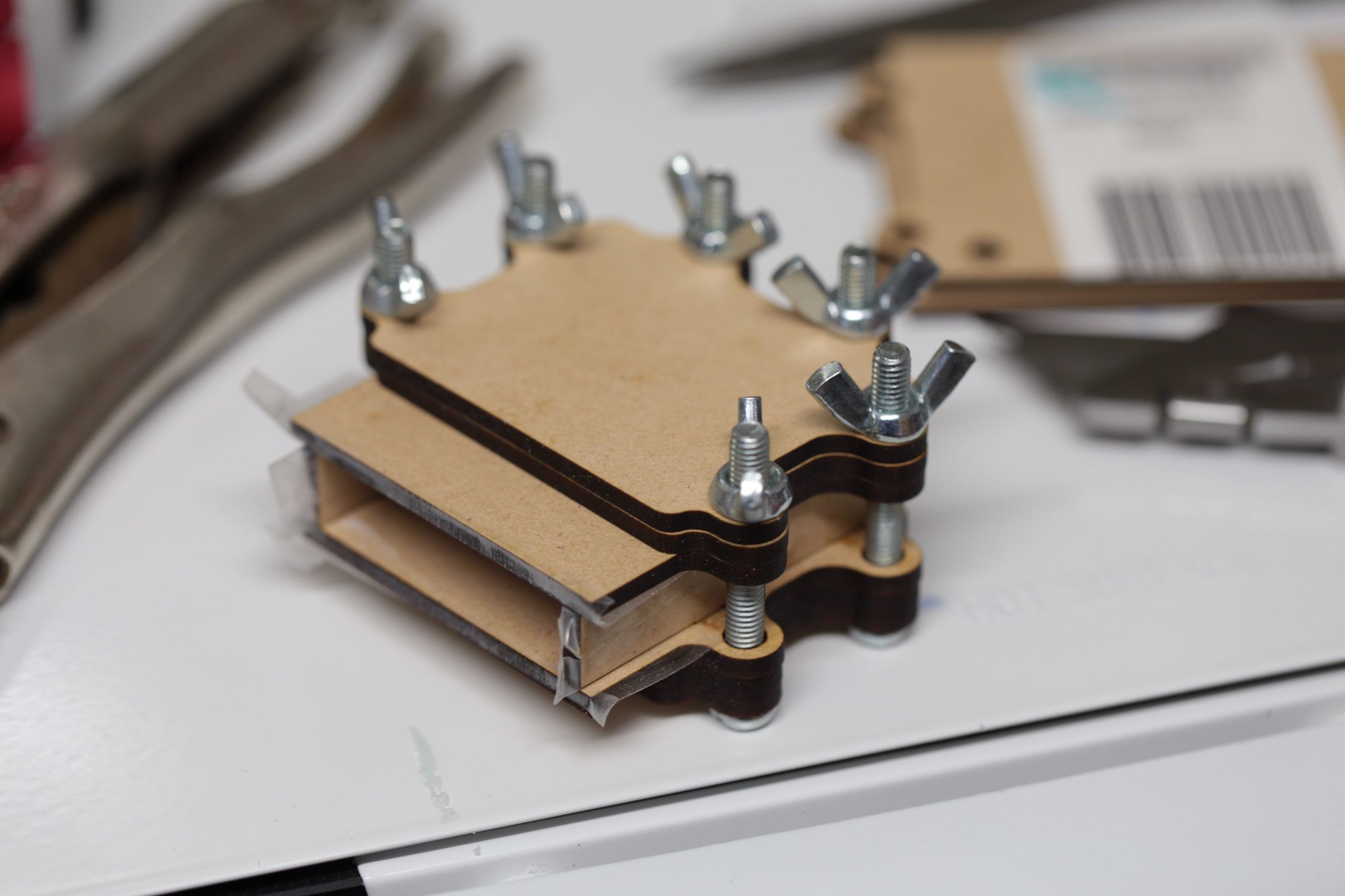
Once the silicone mold was made, I designed a simple jig on my laser cutter. (Instant value right here) Saves alot of time. and ensures molds are perfectly aligned.
 greg davill
Discussions
Become a Hackaday.io Member
Create an account to leave a comment. Already have an account? Log In.