0%
0%
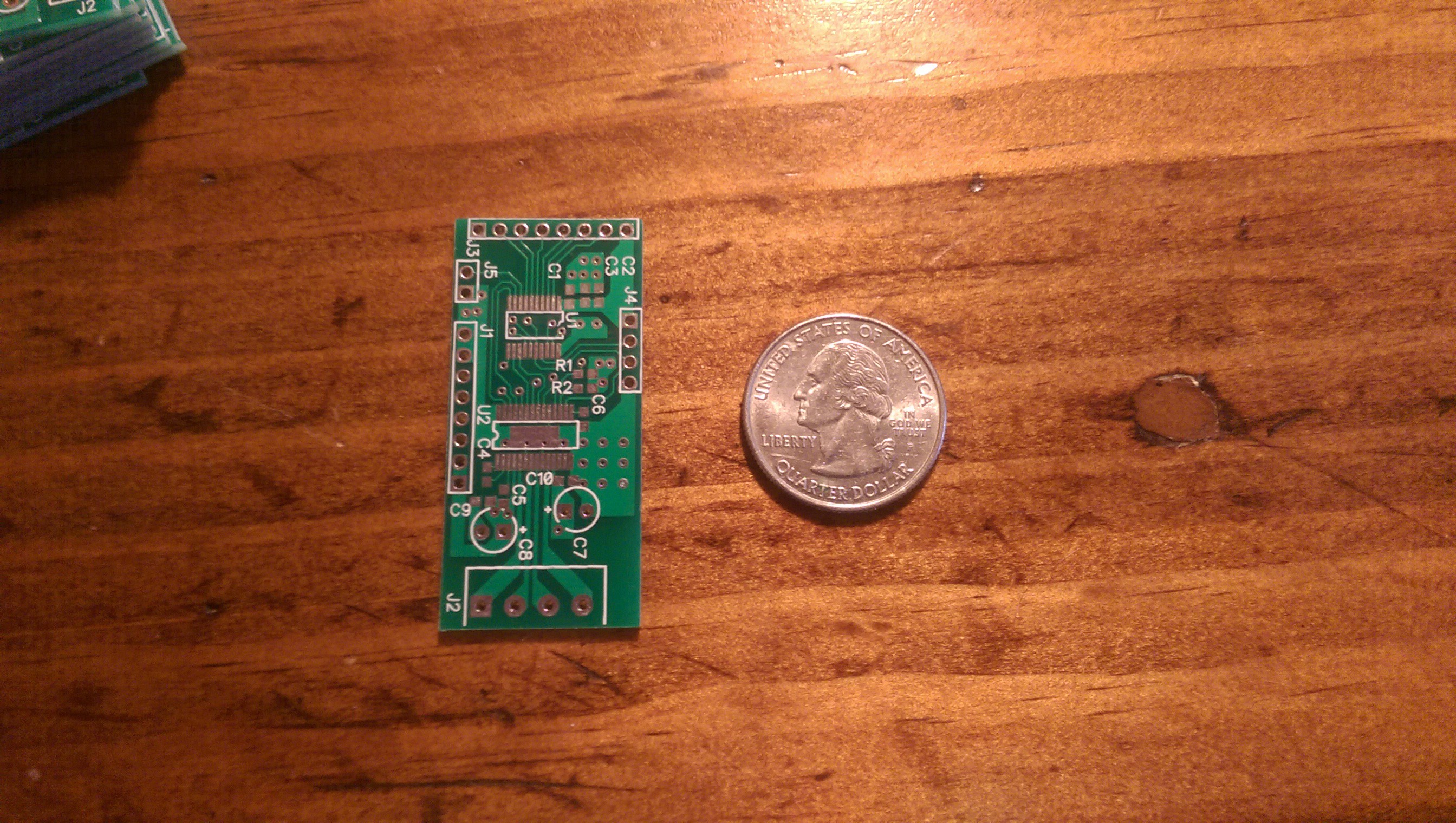
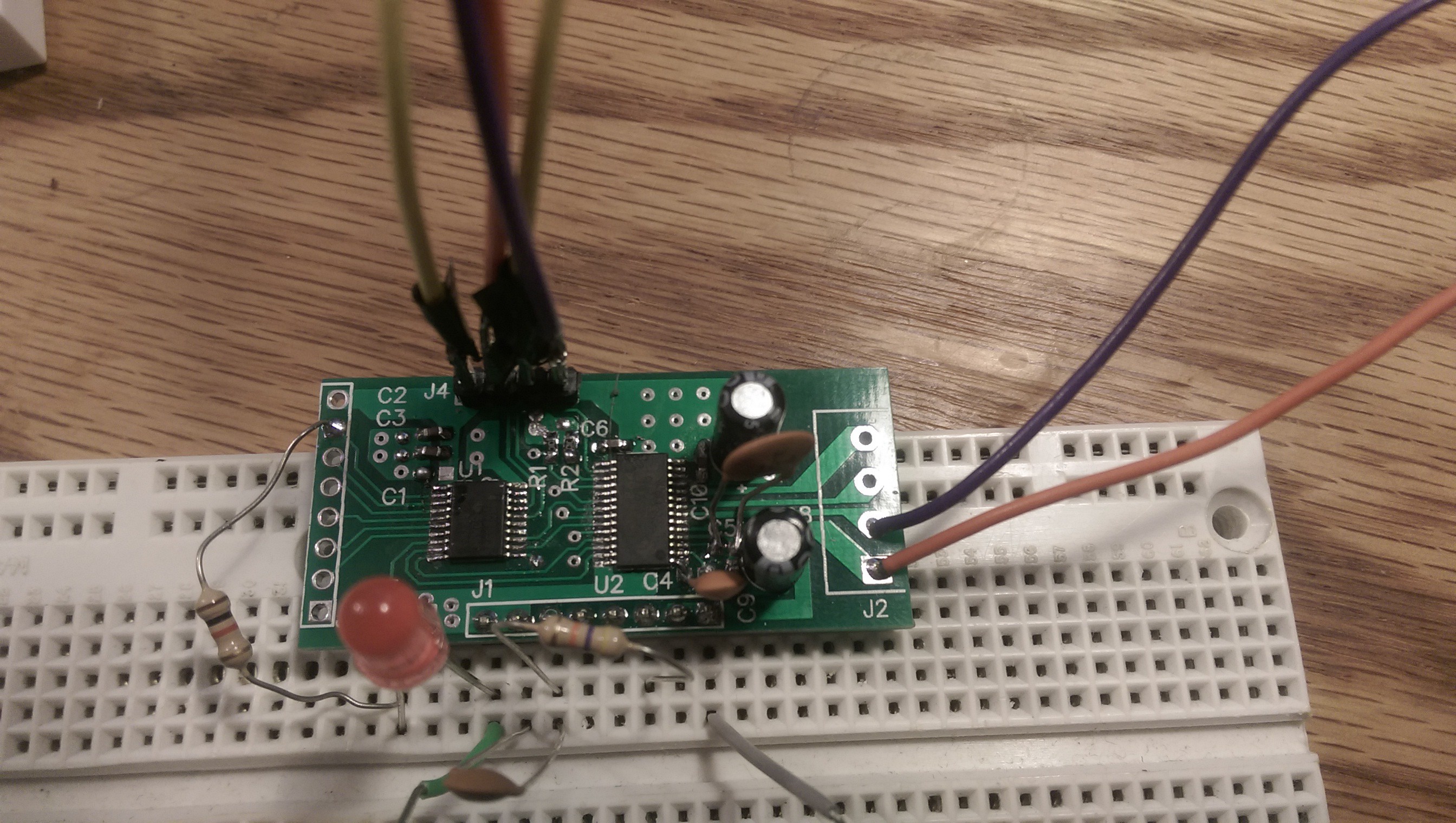
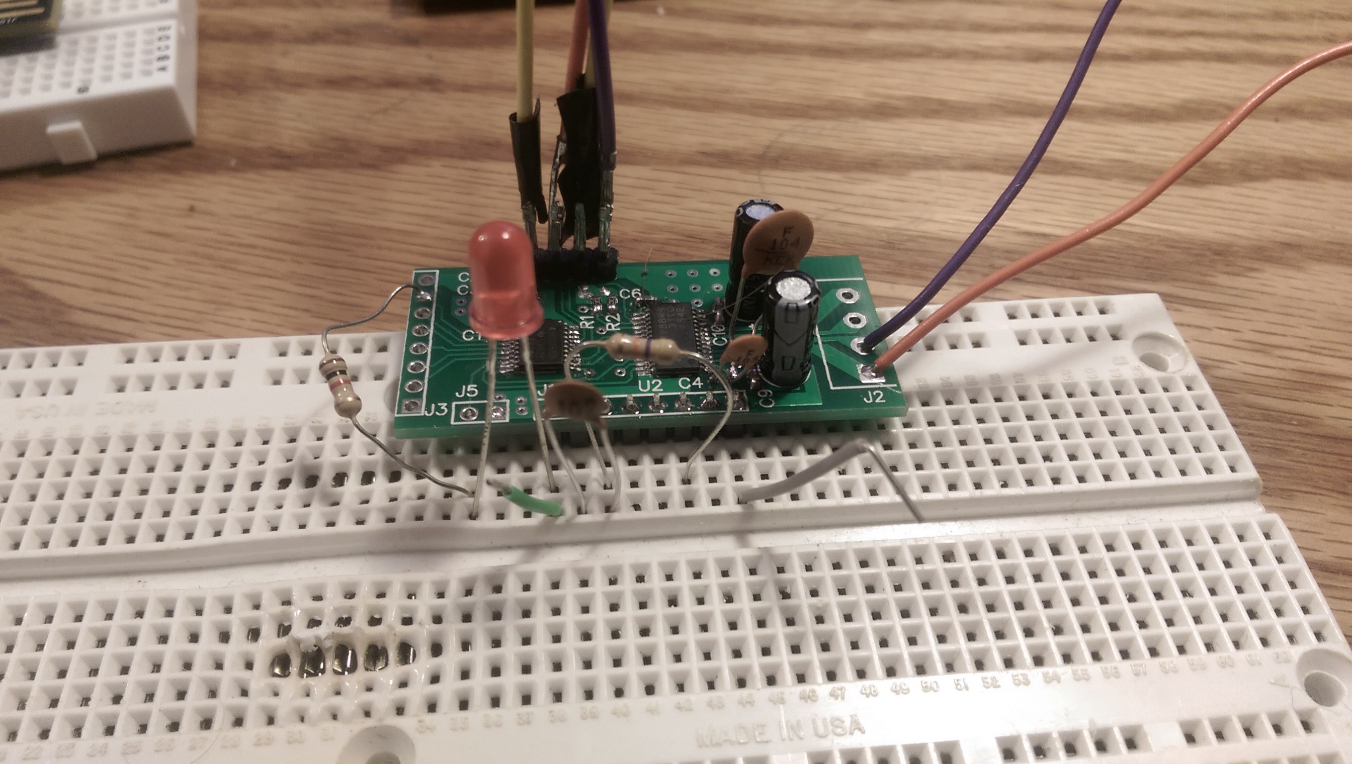
Tiger430 Motor Driver
A programmable motor driver for fun and profit
 Andrew Kowalczyk
Become a Hackaday.io member
Already have an account? Log in.
Just one more thing
To make the experience fit your profile, pick a username and tell us what interests you.
Pick an awesome username
hackaday.io/
Your profile's URL: hackaday.io/username. Max 25 alphanumeric characters.
Pick a few interests
Projects that share your interests
People that share your interests
 John Taylor
 Krockwell
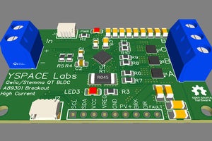
 YSPACE Labs
 Frank Herrmann
Hi, very cool project! I love your board. I know very little about circuits, just learning. I am wondering, is your power supply starting AC? I see that you have capacitors near where the power comes in. Are those needed if your incoming power is DC? If so, can you explain the purpose? Thank you. Also, could you run that board on 12V ? I am interested in your project because I would like to control 2 (larger) DC motors with Arduino and the DRV8844. I was planning to use a 12v battery as the power source, and also include a solar charging controller. (I would guess that I'd need diodes to block the charger from sending juice to the Arduino as well but, not sure).