Hi just finished fixing a list of about 15 issues on github. This resulted in a new firmware version update and a new hardware iteration - minor with just a few values of some resistors changed. One of these was particularly interesting.
As discussed with @Ted Huntington via the comments the other day, the high voltage inverter in these units jumps from 3.3V input to a configurable output voltage that is now set to 380V to fit the SBM-20 Geiger tube. To achieve this long jump, some components are critical to the design, such as the MPSA42 transistor and the 2.2mH inductor. For the latter, some of those building this circuit were having some issues, not being able to obtain the target voltage, or in some cases needing to change (lower) the inductor frequency to get the last push to the target. I did my best to indicate the right sources for the inductors, but in some cases this was not enough.
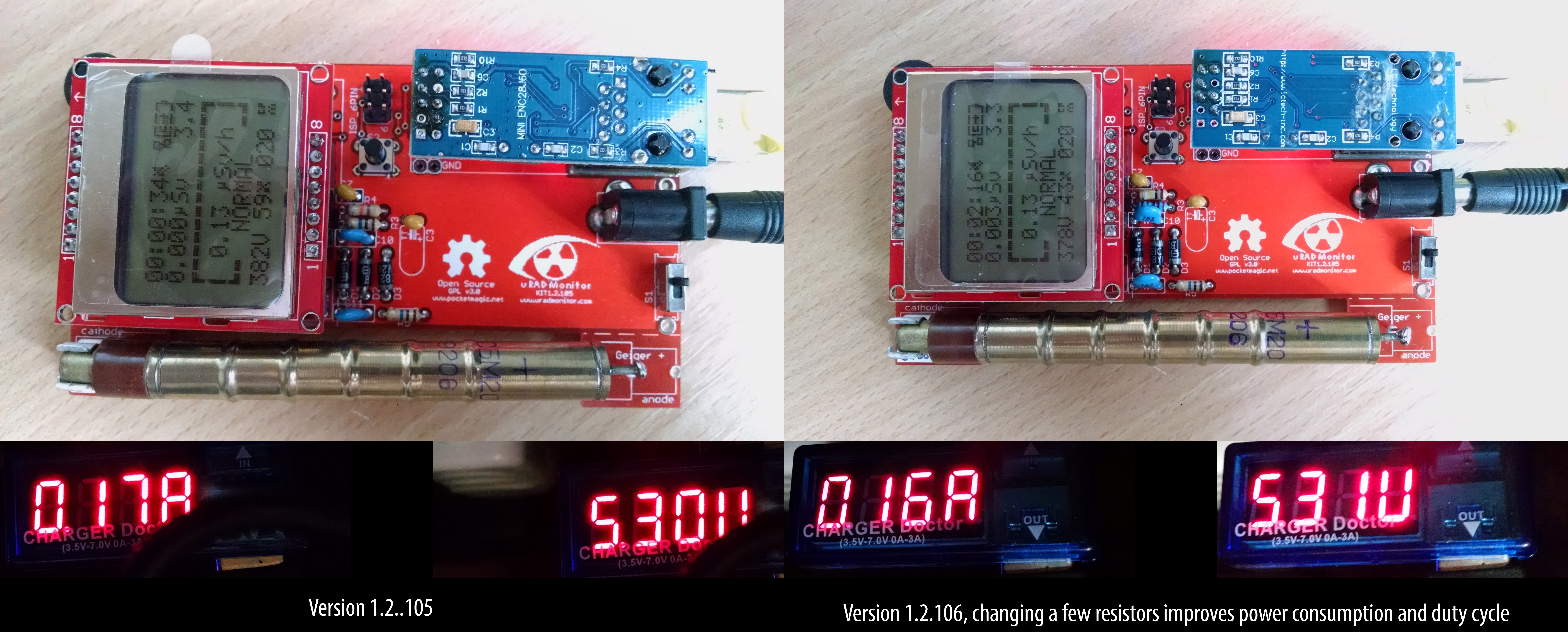
So what happened with the github issues? Well Wolferl1 pointed out some issues with the values I've been using. And indeed, he was right. I changed those right away, and this brought some immediate improvements, such as lower PWM duty cycle to the high voltage inverter, and lower power consumption:

But the lower duty cycle gives more margin to the inductor working interval, lowering the criticality of this component. His suggestions went further like using a 47M resistor in the high voltage divider circuit used for feedback, but I decided to go with more common components.
Yet, another example of team work, making this product better. Open source rules!
 Radu Motisan
Discussions
Become a Hackaday.io Member
Create an account to leave a comment. Already have an account? Log In.