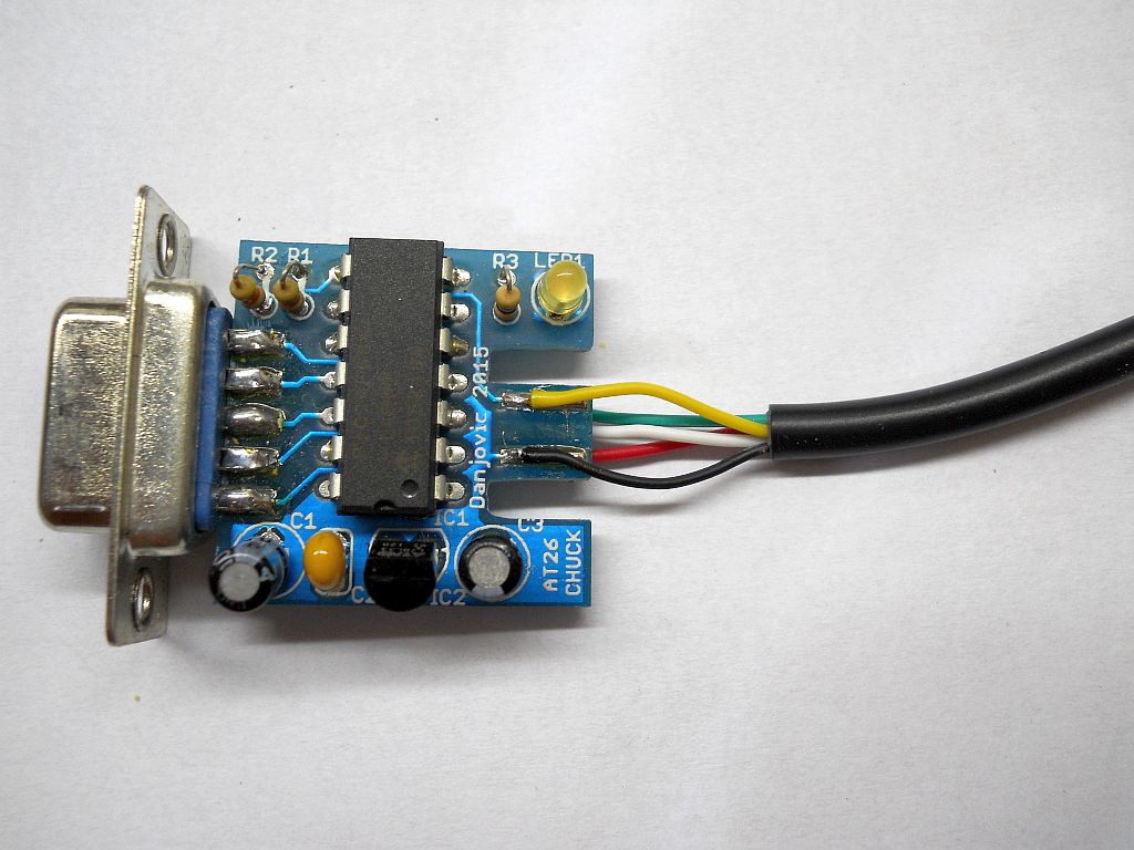
The female connector was taken from a cheap SNES extender. The wire colouring is not equal that from the original controller, so the wires must be identified prior to soldering

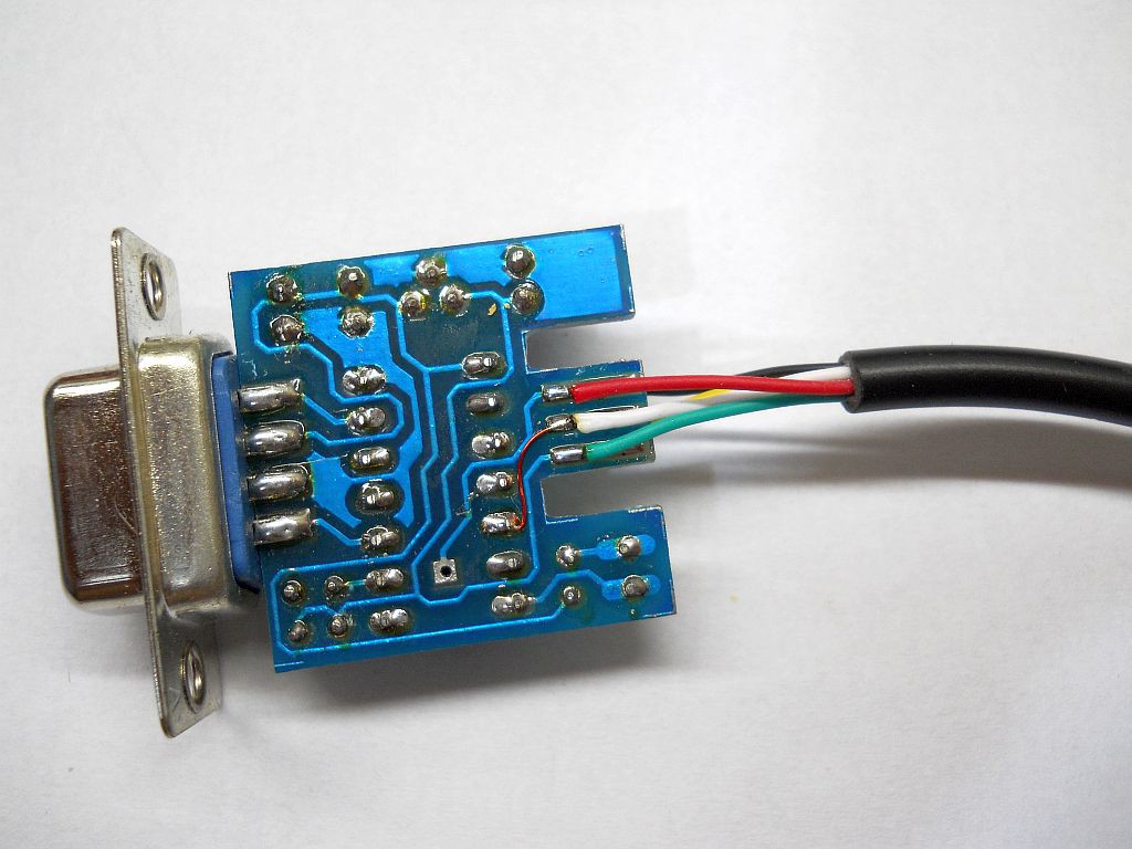
The overview of the assembly is show below. 3 of the wires are soldered on the bottom (lower) face, while the others are soldered on the top layer

Below is a close view of the wiring, showing the top face.

The bottom face is shown below. Notice the modification from pin 7 of the micro-controller to the central pad.

 danjovic
Discussions
Become a Hackaday.io Member
Create an account to leave a comment. Already have an account? Log In.