 danjovic
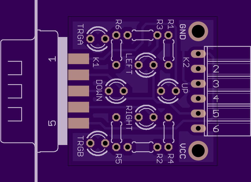
The design of the AT26 Chuck took into account the eventual need for programming/reflashing the microcontroller. It means that the PGC PGD and MCLR pins are available on the Joystick connector. Hence an auxiliary board was designed to connect the signals of the ISP to the respective pins in the DB-9. As a bonus such board provides LEDS to test the activation of the Joystick lines (Up, Down, Left, Right, Trigger A and Trigger B).
The board also have two attaching points for attaching a a power supply by using alligator whenever the PICKIT is not being used to power the 'chuck and test boards.
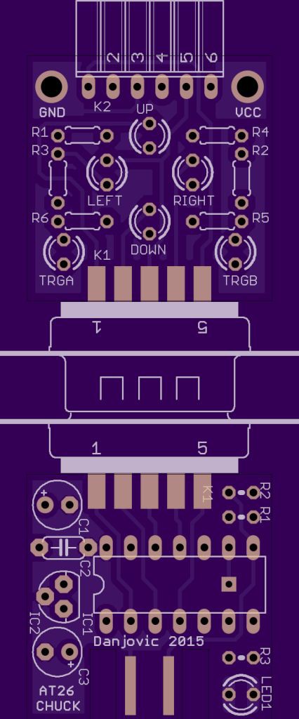
When programming/testing Both boards shall be connected as below:
Discussions
Become a Hackaday.io Member
Create an account to leave a comment. Already have an account? Log In.