A fundamental rite of passage is getting your embedded system to blink an LED. In this post, I'll show you how to take a Raspberry Pi 3 fresh out of the box and get an LED blinking on the CAT Board.
(If you're already experienced with the RPi, then a lot of this post will be redundant for you. However, I've found it useful to document processes so I can repeat them reliably at a later date when the details have grown fuzzy.)
Install the OS
The first thing to do is install an operating system (OS) on the RPi:
- Get the Raspbian OS for the RPi and unzip it on the PC.
- To write the OS image to the SD card, get the Win32DiskImager and install it on the PC.
- Use the Win32DiskImager to write the Raspbian OS to an SD card inserted in the PC. (This will take a while.)
SSH Over Ethernet
I'm going to use the RPi by connecting to it over a network SSH connection from my PC:
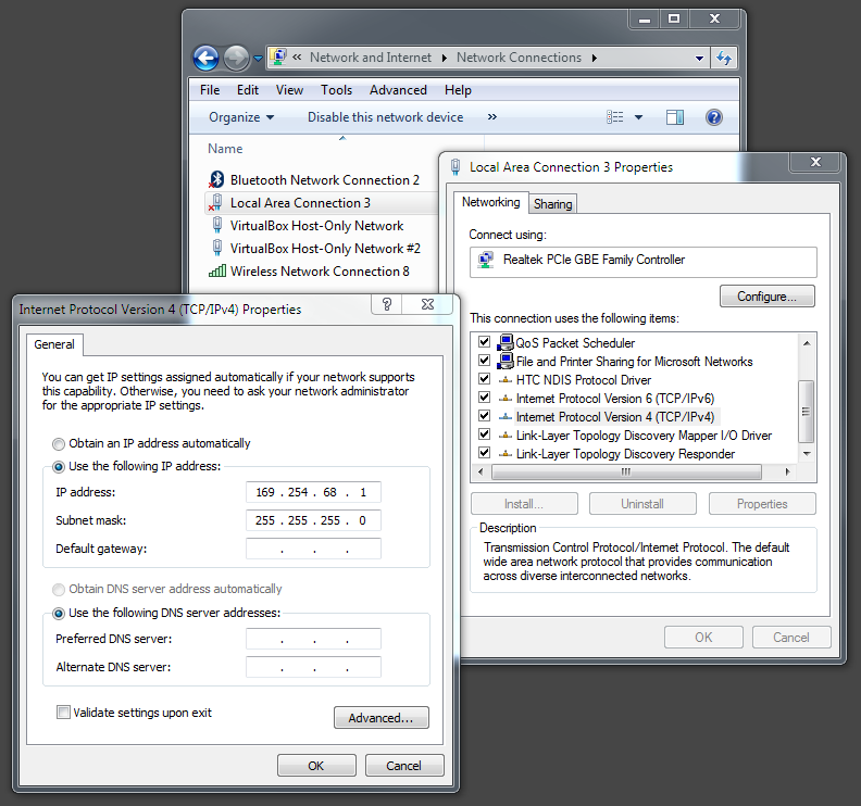
- Look in Network Connections to find the IP address of an Ethernet port the RPi can attach to.
![]()
- Go into the SD card and make a copy of the cmdline.txt file. Then rename the copy cmdline.normal. (This saves a copy of the original configuration in case I want to go back to it later.)
- Edit the cmdline.txt file to assign an IP address to the RPi that's identical to the one for the Ethernet port except for the last field. In my case, I selected 169.254.68.2 and appended it to the first (and only) line in the file to get:
ip=169.254.68.2 - Save the cmdline.txt file and eject the SD card from the PC.
- Insert the SD card into the RPi.
- Connect the RPi to the PC's Ethernet port with a cable.
- Apply power to the RPi and let it boot up.
- To talk to the RPi using SSH from the PC, get PuTTY and install it.
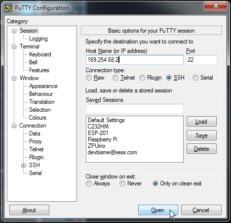
- Run PuTTY and SSH into the RPi at address 169.254.68.2:
![]()
- Login to the RPi using the account "pi" and the password "raspberry".
SSH Over the Wireless Network
You can do everything over the wired Ethernet, but I prefer the convenience of using my local wireless network.
- To allow the RPi to access the local wireless network, open the /etc/wpa_supplicant/wpa_supplicant.conf file and append the following lines:
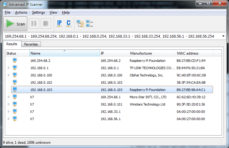
network={ ssid="XESS" psk="whatever_my_wireless_password_is" } - Reboot the RPi and then look for the wireless connection using something like Advanced IP Scanner:
![]()
- Now disconnect the Ethernet cable and use PuTTY to SSH into the RPi over the wireless network using the IP address found in the last step (192.168.0.103).
Enable File Sharing
Sharing files between my PC and the RPi lets me use a familiar editor to write source that can then be dropped onto the RPi.
- To share files between the RPi and the PC, install Samba on the RPi like so:
$ sudo apt-get update $ sudo apt-get install samba $ sudo apt-get install samba-common-bin - Edit the /etc/samba/smb.conf file and add the following at the bottom:
- Start the Samba server running on the RPi:
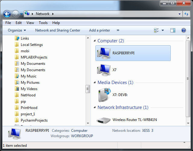
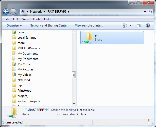
- Open the Network window on the PC. The RPi should be visible there:
![]()
- Double-click the RASPBERRYPI icon and the shared directory will appear. Files can be transferred between the PC and RPi there:
![]()
[pi]
path=/home/pi
writeable = yes
browseable = yes
only guest = no
create mask = 0777
directory mask = 0777
public = yes
Also, change the name of the workgroup to whatever is being used for the Windows PC:
workgroup = XESS
sudo service smbd start
Reconfigure the RPi
Before the RPi can be used to program the CAT Board FPGA, a few of its configuration settings need to be adjusted:
- On the RPi, type the command:
sudo raspi-config
- In the initial screen that appears, select option 1 for expanding the linux partition. (The stock Raspbian OS image creates a 4GB partition. This won't be enough to compile the FPGA tools. Believe me, I tried.)
![]() As an alternative, you can also use the command-line version to do the same thing:
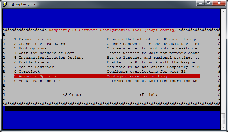
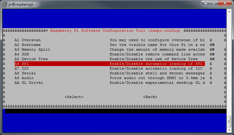
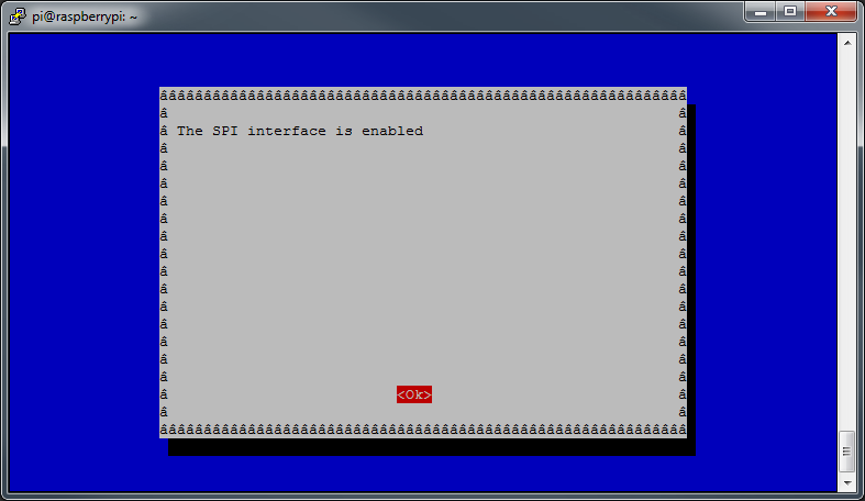
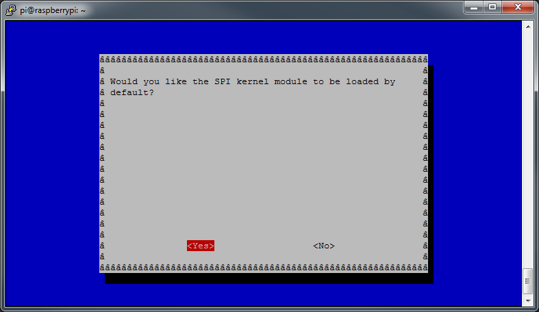
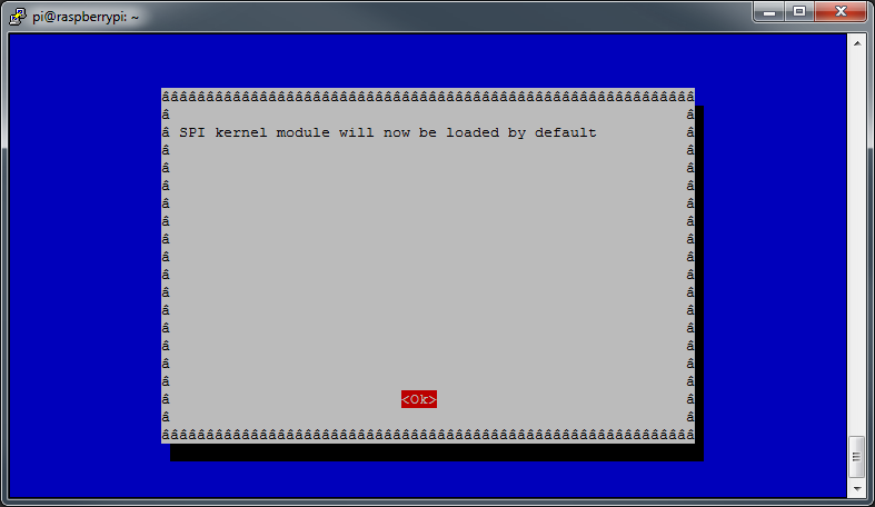
As an alternative, you can also use the command-line version to do the same thing:sudo raspi-config --expand-rootfs - Communicating with the CAT Board also requires the use of the RPi's hardware SPI port. That is enabled using the following screens:
![]()
![]()
![]()
![]()
![]()
![]()
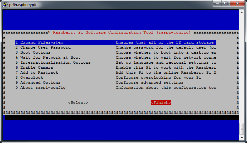
- Finally, close raspi-config and reboot the RPi to let the changes take effect.
![]()
Install the FPGA Software Tools
There are five software packages needed for compiling bitstreams for the Lattice iCE40 HX FPGA on the CAT Board:
- First, install some precompiled packages that the FPGA tools depend upon:
all_deps="build-essential clang bison flex libftdi-dev libreadline-dev gawk tcl-dev libffi-dev git mercurial graphviz xdot pkg-config python3" sudo apt-get install $all_deps - Build the icestorm tools that create bitstreams for the iCE40 FPGAs:
cd /opt sudo git clone https://github.com/cliffordwolf/icestorm.git cd icestorm sudo make sudo make install - Build the arachne-pnr tool that places and routes the circuitry with the FPGA:
cd /opt sudo git clone https://github.com/cseed/arachne-pnr.git cd arachne-pnr sudo make sudo make install - Build the Icarus tool that simulates the operation of the circuitry described by HDL source files. (This takes a long time. Icarus is used to test the functions of the yosys tool that's built next. If you trust the build process and don't want to run the tests, then you don't need Icarus.)
cd /opt sudo apt-get install autoconf gperf sudo git clone git://github.com/steveicarus/iverilog.git cd iverilog sudo sh autoconf.sh sudo ./configure sudo make sudo make install - Build the yosys tool that synthesizes logic circuitry from Verilog source files:
cd /opt sudo git clone https://github.com/cliffordwolf/yosys.git cd yosys sudo make config-clang sudo make sudo make test sudo make install - Install the litterbox tool that transfers a bitstream file from the RPi into the FPGA on the CAT Board:
sudo pip install litterbox
Create the Blinky Design
Finally, I've reached the point where the blinky is designed. The blinky only does one thing: it blinks an LED on and off once each second.
The CAT Board has four LEDs and a 100 MHz clock connected to the iCE40 FPGA. So all I need is a counter driven by the clock that increments to 50,000,000 and then toggles one of the LEDs in a repeated fashion. Here's some Verilog code I stored in the blinky.v file that does that:
module blinky(clk_i, led_o);

input   clk_i; // Clock input.
output  led_o; // LED output.

reg     [25:0] cnt; // Counter with max count of 2**26=67,108,864.
reg     tgl; // Toggle flag for driving LED.

assign led_o = tgl; // Connect LED to toggle flag.

always @ (posedge clk_i) // Do this on every rising edge of the clock.
begin
    if (cnt == 50000000-1) // Has the counter reached its limit?
    begin
        tgl = !tgl; // Flip the LED from OFF-to-ON or ON-to-OFF.
        cnt = 0;    // Reset the counter.
    end
    else // Keep incrementing counter until it reaches its limit.
        cnt = cnt + 1;
end

endmodule
In addition to the Verilog code, I need a way to tell the FPGA tools what pins of the FPGA are connected to the clock signal (pin C8) and the LED (LED1 is attached to pin A9). That information is stored in a pin constraints file called blinky.pcf:set_io clk_i C8 set_io led_o A9
Compile the Blinky Design
The start of the FPGA compilation process begins with yosys. It parses the Verilog source and synthesizes a set of interconnected logic gates that implement the desired function. The gates and their interconnections are stored in a BLIF (Berkeley Logic Interchange Format) file.yosys -p 'synth_ice40 -top blinky -blif blinky.blif' blinky.vThen the BLIF and pin constraints files are sent to arachne-pnr which maps the gates into the logic array of the iCE40 HX8K FPGA and programs the switches in the connection matrix to connect the gates to each other and to the requested I/O pins.arachne-pnr -d 8k -o blinky.asc -p blinky.pcf blinky.blifThe blinky.asc file contains an ASCII representation of the settings for all the programming bits in the FPGA. The icepack tool turns this into a bitstream file with a binary format that can be downloaded into the FPGA.icepack blinky.asc blinky.bin
Load the Blinky Bitstream Into the FPGA
The bitstream file is loaded into the FPGA with the litterbox tool:
sudo litterbox -c blinky.binAfter the FPGA configuration is complete, LED1 on the CAT Board will start to blink on and off once every second.
The bitstream can also be stored in the serial flash so the FPGA will start to blink whenever power is applied to the CAT Board:
sudo litterbox -p blinky.binHere's a video that shows the compilation and downloading steps for the blinky design: Dave Vandenbout
 As an alternative, you can also use the command-line version to do the same thing:

Discussions
Become a Hackaday.io Member
Create an account to leave a comment. Already have an account? Log In.
Admittedly, I only figured that "build-yourself" bit only after adding the reference. But then again, not at least for outshining the regular devices from Lattice, I even felt like emphasising it :o) Also, your video is so encouraging, you truly tempted me. I keep thinking about what I would have built, or what you would build if you did it again. It all sounds like a wonderful kickstarter/indiegogo project to me.
Are you sure? yes | no
Well done! The Debian folks now have packages for yosys, arache-pnr and icestorm and albeit litterbox is still missing as a package, I went on and added a reference to your tutorial on https://wiki.debian.org/FPGA/Lattice . If there are ideas of yours on what Debian should do to support FPGA development then please get in touch.
Are you sure? yes | no
There are only 3-4 CAT Boards in the whole world so I doubt litterbox is of much use to anybody else, but thanks for the effort and taking the time to read!
Are you sure? yes | no
Awesome. BTW, LOL'd at "litterbox" tool. :-)
Are you sure? yes | no
Good. Come for the FPGA board; stay for the awful jokes!
Are you sure? yes | no