 David Scholten
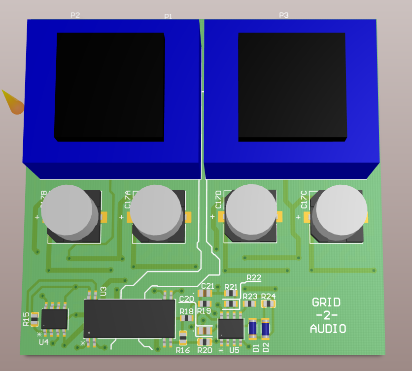
As promised, here is the PCB layout of the Grid-2-Audio module (minus the I/O connectors).
Top view:
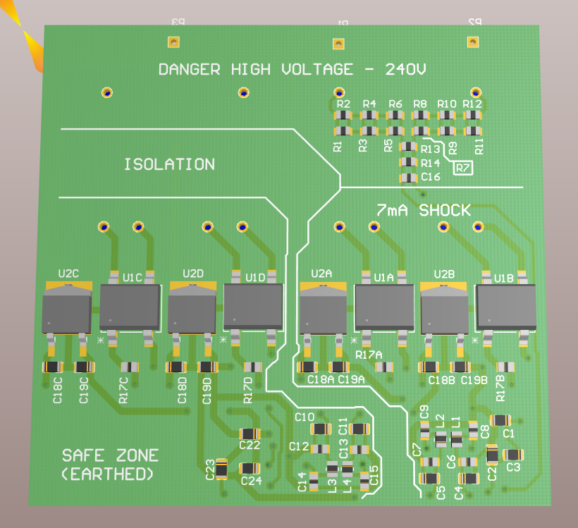
Bottom view:
2D view:
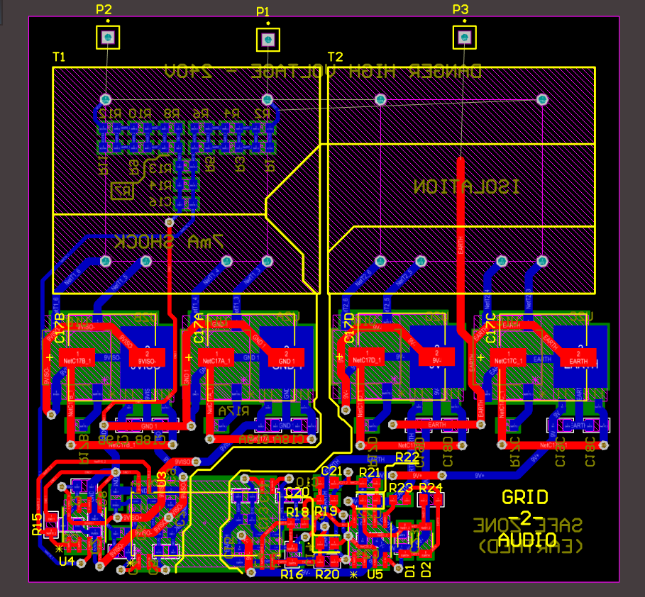
The general philosophy was to divide the board up into three sections, each with an escalating level of danger. The first is the mains section, which exists solely to power the transformers and take a voltage divider. The second is the non-isolated side of the ISO124, which is powered by one of the two transformers and has a 30kOhm connection to active (about a 7mA shock potential). The third section is the isolated side of the ISO124 that is powered by the other of the two transformers. This side is effectively galvanically isolated, physically separated and earthed (earthing is not yet shown in the images).
My only concern at this point is the heat dissipation on the mains side resistive divider and the earthing circulation currents that may degrade the output signal (unlikely).
The next step is to touch up the layout a little bit and get to work on modifying the enclosure to fit the now-larger PCB.
Discussions
Become a Hackaday.io Member
Create an account to leave a comment. Already have an account? Log In.