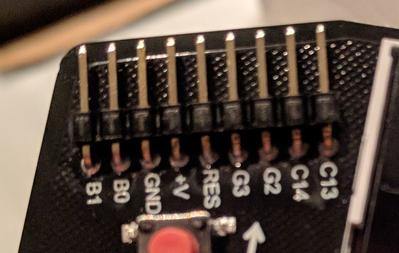
Front view of expansion Header:

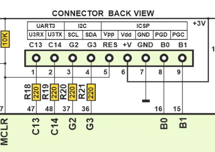
Here is a rear view diagram of the pin header taken from the badge schematic.

These pins can be controlled from BASIC using the edir, ein, and eout commands. The UART on pins C13 and C14 can be accessed from BASIC using uin and uout commands.
G2 and G3 are 5V tolerant but all other pins should be interfaced at 3V.
 Mike Szczys
Discussions
Become a Hackaday.io Member
Create an account to leave a comment. Already have an account? Log In.