 Yann Guidon / YGDES
(Note: Interesting read but superseded)
(note 2, 20151030 : a similar idea is implemented at http://josephknowles.com/2014/10/09/z-80-homebrew-io-board/ but with a 16->1 multiplexer)
It does not seem reasonable to implement capacitive keys (yet).
I have to stick to dumb logic and smart ideas.
There are not many keys so the required logic will not be too hard. There is the hex keypad and the command keys, overall 32 keys or less. It does not seem necessary to use an array for the scan, particularly because the "priority encoder" logic could become tricky. (Update: later, I found the 74HC148 priority encoder in a local store...)
Fortunately the user interface does not need simultaneous key presses. The keys count could even be lowered if the "command" keys are "folded" into or "shared" with the hex keys. But I'm not making one of those electronic music instruments with weird "modes" and hidden/obscure combinations to access menus... I know that some love minimalism like #Unhappy Hacking Keyboard but I can live with more keys, the more the better. Where is the "homebrew appeal" or the "physical computing charm" otherwise ? Give me keys !
 So the challenge is to 1) scan all the keys 2) provide a reliable information when more than one key is pressed 3) get the timings right.
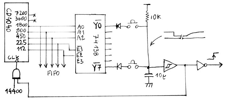
The starting point is the scan of the keys. We can use the running counters from the display board's CD4040 or even generate a local lower frequency with another one (so there is only one signal to send from P1B to P1A).
OK now we have a 5-bits free-running counter that wraps around at least 100 times per second. The output goes to several 74HC138, each output is connected to a single key. The 3->8 decoders can be scattered across the PCB, we are not constrained by the geometry of an array.
The 74HC138 outputs are normally held high. One output goes low at a time. So when the four 74HC138 are connected to the 5-bits counter, all the outputs will go low in sequence, one after another.
Then the main "trick" is to make a big "wired OR" circuit with all the outputs. Each output is followed by a diode in series with one of the keys. The other terminal of all the keys is connected to a common "sense" signal, pulled-up by a 10K resistor.
- When no key is pressed, each decoder output is pulsed low but there is no connection, the circuit is broken by all the open keys. Nothing happens.
- When a key is pressed, there is a connection between the driving decoder and the common signal. Most of the time, the decoder's output is high, while the common signal is pulled high, so nothing happens. But when the 138's output is pulled low, current can start flowing through the diode and the common signal goes low (actually, about 0.8V, if we count the output impedance and the diode forward voltage).
- When more than one key is pressed, the diodes prevent shorting the decoders outputs when one of the keys is selected (there would be a direct connection between high and low logic levels).
Now we get a low pulse on the common signal, each time a key is pressed and it is being probed. The next step is to sample this signal.
The common signal is combined with the input frequency to create a rising edge in the middle of the current cycle, so the counter's value can be stored in a 74HC273. This value is updated each time a pressed key is probed so the '273 could oscillate between two or more values.
The priority encoder is implemented by sampling the '273 at the end of a scan cycle. If several keys are pressed simultaneously, only the key with the highest scan code will be considered.
A more compact version is possible if the scan counter's clock can be inhibited (let's indulge in clock-gating). The CD4040's clock input is ANDed with the pulled-up common signal:
- When no key is pressed, the counter roams freely.
- When the count reaches the position of the pressed key, the common signal is pulled low, the AND stays low, which inhibits the counter's clock. The counter's value is frozen as long as this key is held down.
Prioritisation of the scan code is inherent and "first press first serve". The code is send on press, not release.
The other hidden advantage is the ease of implementing a debounce circuit: a simple capacitor (10µF alu ?) between the common signal and 0V, to delay the rising edge. The common signal should be buffered with a Schmitt Trigger circuit to prevent parasites. The output of this buffer can then send a strobe to the other circuits, telling them to sample the counter's value.
It's not very complex :-) The only drawback is we can't use this easily to control the TIL311's blanking to reduce the current and luminosity.
PS: I just found 20years old scraps from an even older keyboard that I completely took apart (I think I wanted to make a MC6809 SBC as a teen). The keys are bulky but they contain a diode ! The first prototype will be awesome and clicky :-D
Discussions
Become a Hackaday.io Member
Create an account to leave a comment. Already have an account? Log In.