zakqwy
-
auto dice
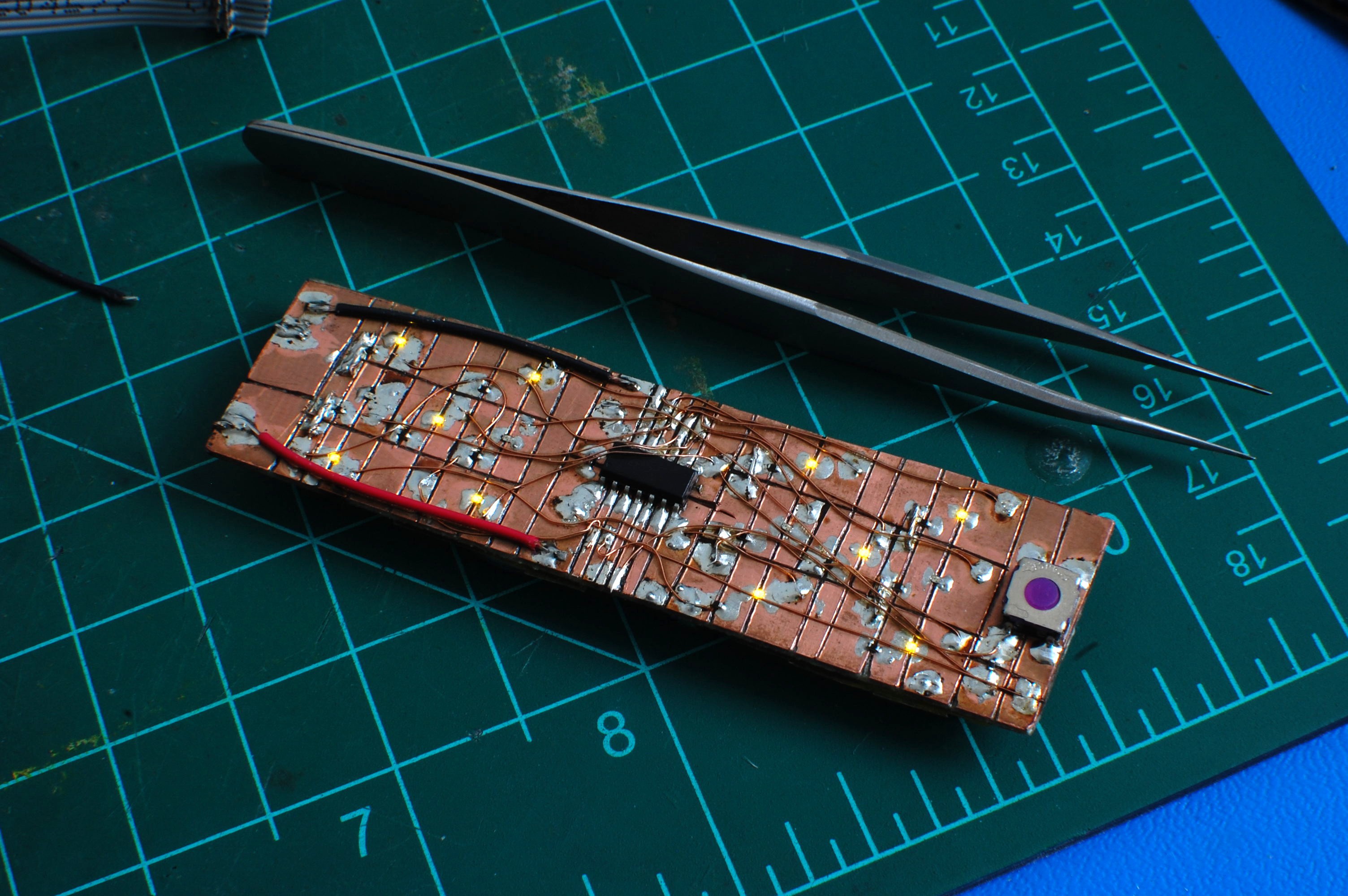
07/30/2016 at 22:02 • 0 commentsTime for more tedious FR4 carving and soldering. This project is my take on a classic kit (see: here, here, here, here, etc). Like many of the other options available, my build uses the uncertainty of button press time to generate a random roll; as long as the pushbutton is held down, the microcontroller rapidly runs through all available options before stopping when the button is released. I think the two-dice-in-one setup is ideal--great for Catan, Monopoly, etc.
![]()
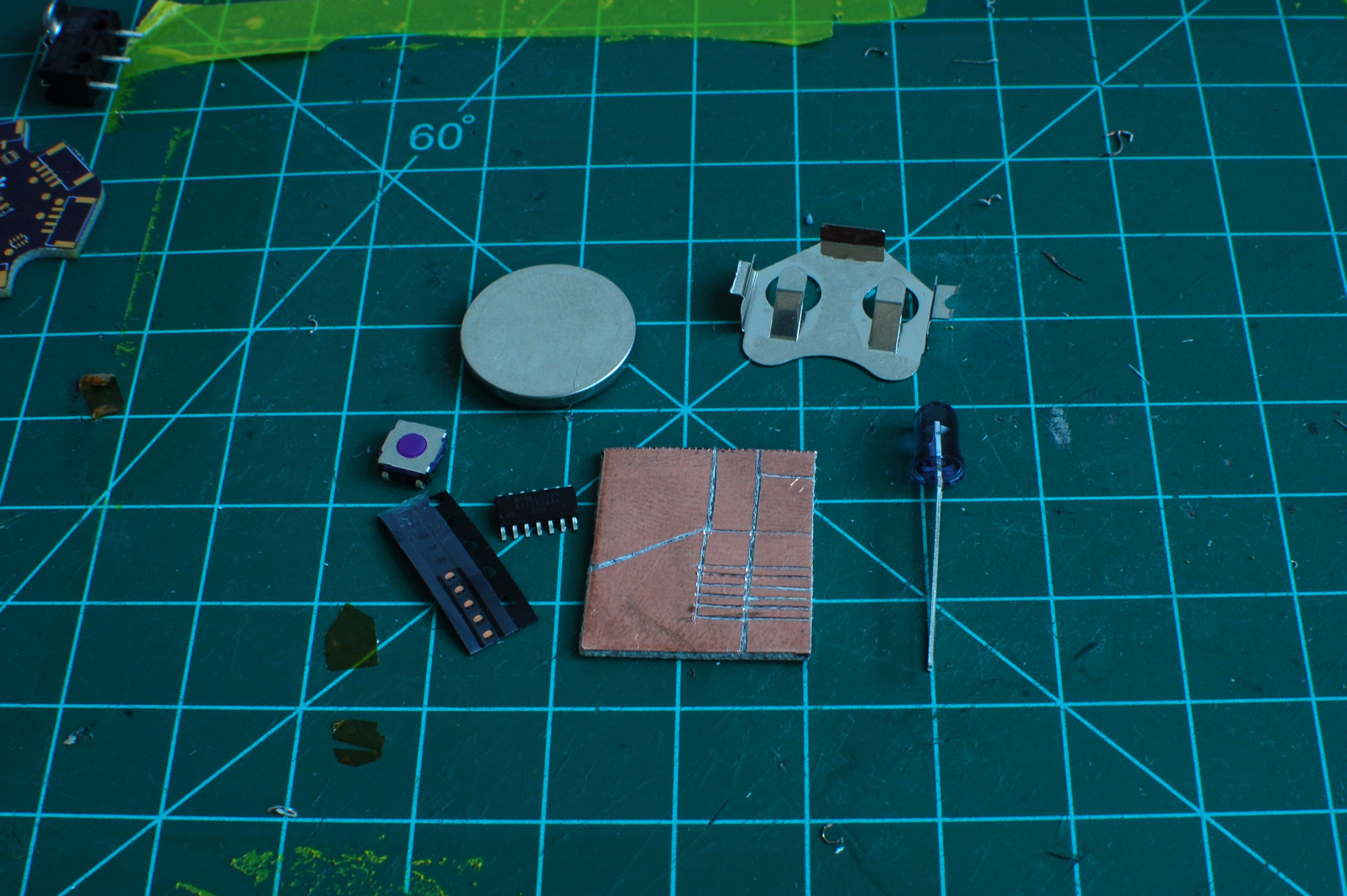
BOM:
- ATtiny44A SOIC microcontroller
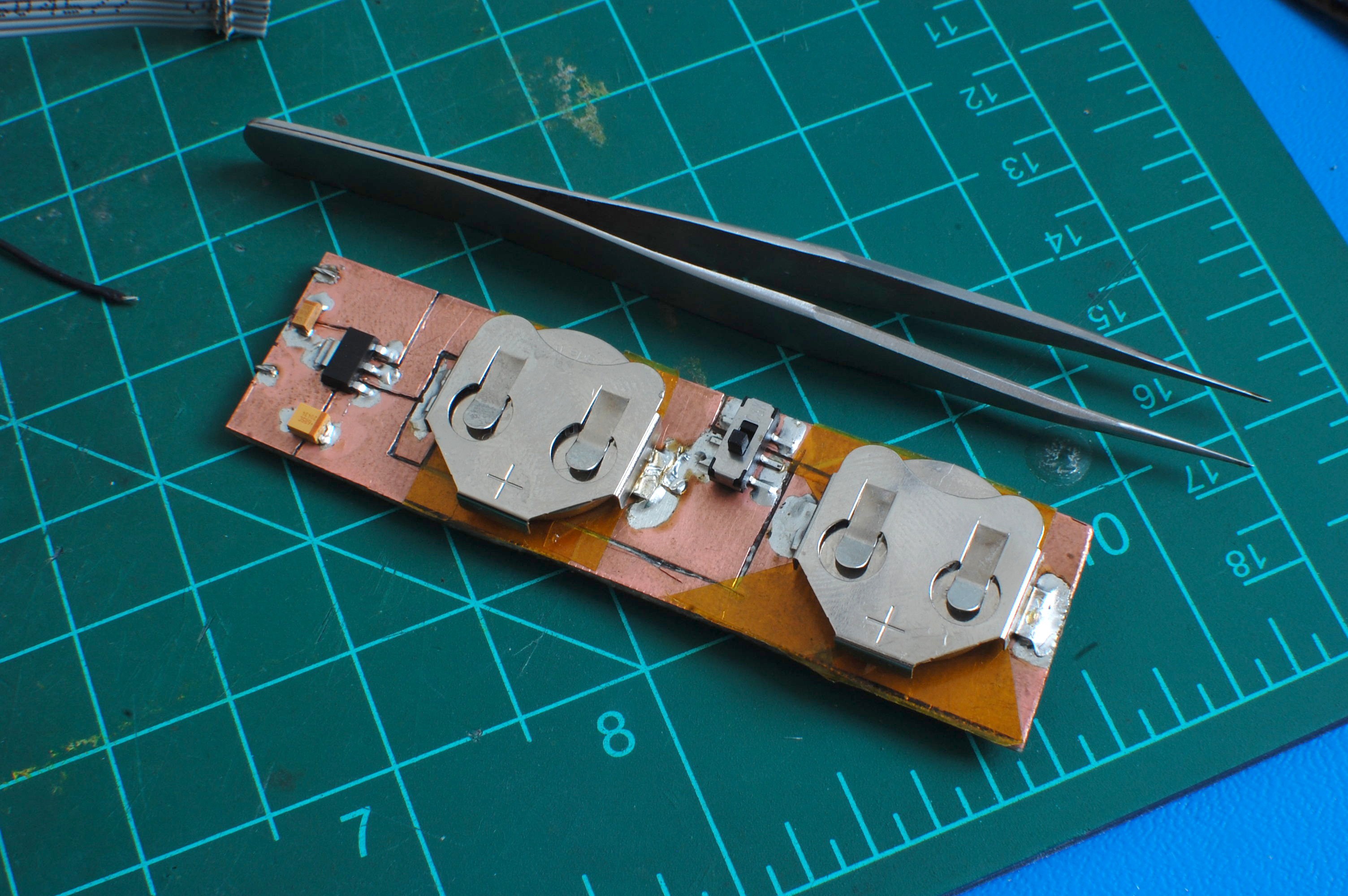
- CR2032 batteries with trimmed clips (2)
- Rohm 580nm PICOLEDs (14)
- 6.8 and 10 uF tantalum capacitors, 10vdc
- 150 (14) and 10k (1) resistors
- 0.1 uF bypass capacitor
- C&K SMD pushbutton, purple, IP67, 6.2x6.2mm
- 5vdc LDO, SOT223, 1A
- DPDT SMD switch
- Double-sided 1/16" FR4
- Kapton tape
- 26 AWG and 34 AWG wire
![]()
The circuit is pretty simple; the LEDs are arranged in a 7x2 matrix, which seemed reasonable for dice and made the code simple. Even better, the seven anodes run into PORTA while the two cathodes are wired to PORTB. I included a hardware on-off switch to avoid battery drain issues, although I suppose good use of the watchdog timer could render this unnecessary. I dunno, I like hardware switches. The mess of wiring and stuff on the front is secured with a liberal coat of spray polyurethane.
If you _really_ want to know how I put this together.. I actually filmed the whole thing, including an unnecessary amount of running commentary. The build took nearly 4 hours but a fair bit of that is explaining parts, tools, technique, etc. Also, the audio for the first 12 minutes or so stinks, as I forgot to open the back of my GoPro. You've been warned...
Firmware:
/* auto dice by Zach Fredin, July 2016 zachary.fredin@gmail.com Released under the terms of the MIT License. The MIT License (MIT) Copyright (c) 2016 by Zach Fredin Permission is hereby granted, free of charge, to any person obtaining a copy of this software and associated documentation files (the "Software"), to deal in the Software without restriction, including without limitation the rights to use, copy, modify, merge, publish, distribute, sublicense, and/or sell copies of the Software, and to permit persons to whom the Software is furnished to do so, subject to the following conditions: The above copyright notice and this permission notice shall be included in all copies or substantial portions of the Software. THE SOFTWARE IS PROVIDED "AS IS", WITHOUT WARRANTY OF ANY KIND, EXPRESS OR IMPLIED, INCLUDING BUT NOT LIMITED TO THE WARRANTIES OF MERCHANTABILITY, FITNESS FOR A PARTICULAR PURPOSE AND NONINFRINGEMENT. IN NO EVENT SHALL THE AUTHORS OR COPYRIGHT HOLDERS BE LIABLE FOR ANY CLAIM, DAMAGES OR OTHER LIABILITY, WHETHER IN AN ACTION OF CONTRACT, TORT OR OTHERWISE, ARISING FROM, OUT OF OR IN CONNECTION WITH THE SOFTWARE OR THE USE OR OTHER DEALINGS IN THE SOFTWARE. Uses ATtiny44A microcontroller, because that's what I had on hand. Two dice arranged in a 7 (anode) x 2 (cathode) matrix. Uses 580 nm 0402 LEDs with 150 ohm resistors on each. Includes a 2-CR2032 + 5VDC LDO power supply with a hardware switch. Seven anodes on PORTA [0,1,2,3,4,5,6]. Two cathodes on PORTB [0,1]. Switch (pulled down) on PORTB [2]. Dice diagram: PA2 PA0 PA4 PA3 PA1 PA6 PA5 */ #include <avr/io.h> void updateDice(uint8_t die, uint8_t val) { PORTA = 0; if (die == 0) { //left PORTB |= (1<<PB1); PORTB &= ~(1<<PB0); die = 1; } else { //right PORTB |= (1<<PB0); PORTB &= ~(1<<PB1); die = 0; } switch (val) { case 1: PORTA |= (1<<PA3); break; case 2: PORTA |= ((1<<PA6) | (1<<PA0)); break; case 3: PORTA |= ((1<<PA6) | (1<<PA3) | (1<<PA0)); break; case 4: PORTA |= ((1<<PA2) | (1<<PA0) | (1<<PA6) | (1<<PA5)); break; case 5: PORTA |= ((1<<PA2) | (1<<PA0) | (1<<PA3) | (1<<PA6) | (1<<PA5)); break; case 6: PORTA |= ((1<<PA2) | (1<<PA0) | (1<<PA4) | (1<<PA1) | (1<<PA6) | (1<<PA5)); break; } } void SystemInit(void) { DDRA |= ((1<<PA0) | (1<<PA1) | (1<<PA2) | (1<<PA3) | (1<<PA4) | (1<<PA5) | (1<<PA6)); PORTA = 0; DDRB |= ((1<<PB0) | (1<<PB1)); DDRB &= ~(1<<PB2); //button } int main(void) { uint8_t die = 0; uint8_t d0 = 5; uint8_t d1 = 5; SystemInit(); for(;;) { if (PINB & (1<<PB2)) { PORTB &= ~((1<<PB0) | (1<<PB1)); PORTA |= ((1<<PA0) | (1<<PA1) | (1<<PA2) | (1<<PA3) | (1<<PA4) | (1<<PA5) | (1<<PA6)); d0++; if (d0 == 7) { d0 = 1; d1++; if (d1 == 7) { d1 = 1; } } } if (die == 0) { updateDice(die, d0); die = 1; } else { updateDice(die, d1); die = 0; } } } -
Nikon Remote
06/06/2016 at 02:08 • 3 commentsI take a lot of pictures of stuff I'm working on. I have a super crappy tripod, a basic camera (Nikon D40), and a pretty sweet lens (F1.8). I've found the best way to get good lighting is to use the ambient light I get in through the windows; my walls are white so it's quite diffuse most times of day. However, in order to get the depth of field I want (often F15+ for circuitry) I generally shoot with slow shutters despite the speedy lens. My tripod is so crappy that I end up using the self-timer to ensure the camera doesn't vibrate, which takes time.So, remote control time. I could have bought one off the shelf that does the exact same thing but that is dumb and I like soldering.
![]()
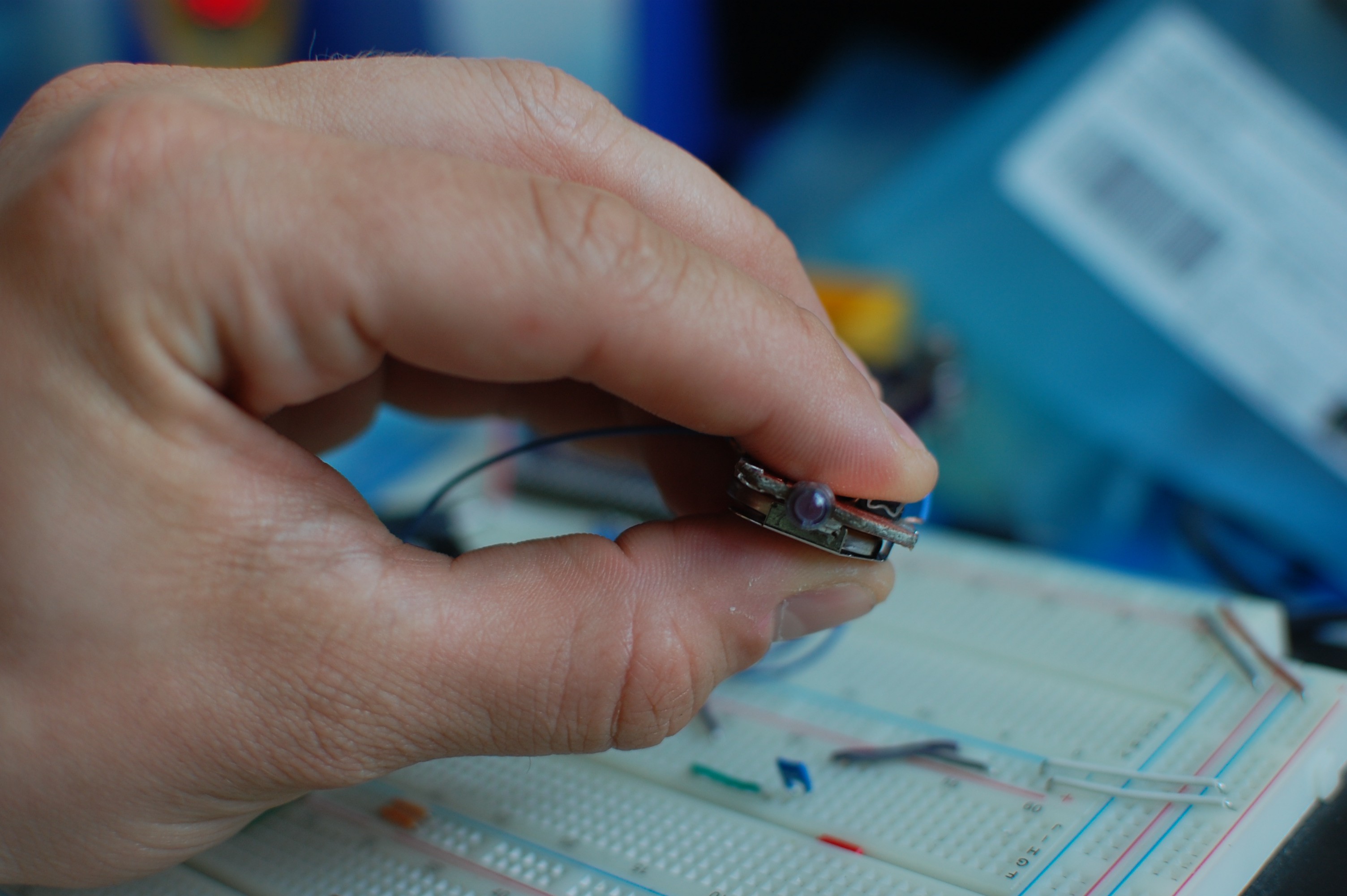
Not much to it. ATtiny44 (left over from #NeuroBytes v0.4), a high-output IR LED, a tiny pink indicator LED (extra from #blinktronicator), a pushbutton switch, a CR2032 battery and holder, and a carved up chunk of FR4. Not shown: current limiting resistors for the LEDs and a bypass cap for the microcontroller.
![]()
Programming connectors were tacked on during hasty firmware development. I re-used the #NeuroBytes v0.9 programmer since it's already a bit outdated.
/*
Nikon Remote Control by Zach Fredin, June 2016
zachary.fredin@gmail.com

Released under the terms of the MIT License.

The MIT License (MIT)
Copyright (c) 2016 by Zach Fredin
Permission is hereby granted, free of charge, to any person obtaining a copy of this software and associated documentation files (the "Software"), to deal in the Software without restriction, including without limitation the rights to use, copy, modify, merge, publish, distribute, sublicense, and/or sell copies of the Software, and to permit persons to whom the Software is furnished to do so, subject to the following conditions:

The above copyright notice and this permission notice shall be included in all copies or substantial portions of the Software.

THE SOFTWARE IS PROVIDED "AS IS", WITHOUT WARRANTY OF ANY KIND, EXPRESS OR IMPLIED, INCLUDING BUT NOT LIMITED TO THE WARRANTIES OF MERCHANTABILITY, FITNESS FOR A PARTICULAR PURPOSE AND NONINFRINGEMENT. IN NO EVENT SHALL THE AUTHORS OR COPYRIGHT HOLDERS BE LIABLE FOR ANY CLAIM, DAMAGES OR OTHER LIABILITY, WHETHER IN AN ACTION OF CONTRACT, TORT OR OTHERWISE, ARISING FROM, OUT OF OR IN CONNECTION WITH THE SOFTWARE OR THE USE OR OTHER DEALINGS IN THE SOFTWARE.

Uses ATtiny44A microcontroller, because that's what I had on hand.
High-output IR LED connected to pin 8 (PA5/OC1B) and VCC; set low to illuminate.
Pink indicator PicoLED connected to pin 7 (PA6) and VCC; set low to illuminate.
Momentary switch supplies power to microcontroller, so it should immediately
execute code.

Nikon timing from https://learn.adafruit.com/ir-sensor/making-an-intervalometer

*/

#include <avr/io.h>
#include <avr/interrupt.h>

uint8_t step = 0; //current stage of IR waveform
uint8_t IRsig[2][18] = {
	{ 62,255,255,255, 78, 12, 47, 15,109, 15,255,255,255,255,255,255,255,158},
	{  1,  0,  0,  0,  0,  1,  0,  1,  0,  1,  0,  0,  0,  0,  0,  0,  0,  0}
};
uint8_t repeat = 0;


void SystemInit(void) {
	DDRA |= ((1<<PA5) | (1<<PA6));
	PORTA &= ~(1<<PA6); //leave pink LED on the whole time
	PORTA |= (1<<PA5); //turn off IR LED to start

	TIMSK0 |= (1<<OCIE0A); //enables Timer 0A output compare match interrupt
	TCCR0A |= (1<<WGM01); //CTC mode
	TCCR0B |= (1<<CS02); //prescales to clk/256 (31.25 kHz)
	OCR0A = 1;

	TCCR1A |= (1<<COM1B0); //toggle OC1B on compare match
	TCCR1B |= (1<<WGM12); //CTC mode
	OCR1A = 12;
	OCR1B = 12; //generates 38 kHz square wave on OC1B

	sei();
}

ISR(TIM0_COMPA_vect) {
	if (IRsig[1][step]) {
		TCCR1B |= (1<<CS11);
		TCCR1A |= (1<<COM1B0);
		TCCR1B |= (1<<WGM12);
	}
	else {
		TCCR1A = 0;
		TCCR1B = 0;
		PORTA |= (1<<PA5);
	}
	OCR0A = IRsig[0][step];
	step++;
	if (step == 18) {
		step = 0;
		repeat++;
		if (repeat == 2) {
			TCCR1A = 0;
			TCCR1B = 0;
			TCCR0A = 0;
			TCCR0B = 0;
			TIMSK0 = 0;
			cli();
		}
	}
}

int main(void) {
	SystemInit();
	for(;;) {

	}
}
I used both timers on the ATtiny44; since the IR LED is hooked up to PA5 (which is OC1B), I used Timer/Counter 1 to generate the 38 kHz square wave and the timer 0 interrupt to toggle said square wave on and off as appropriate, according to the IRsig[][] array.![]()
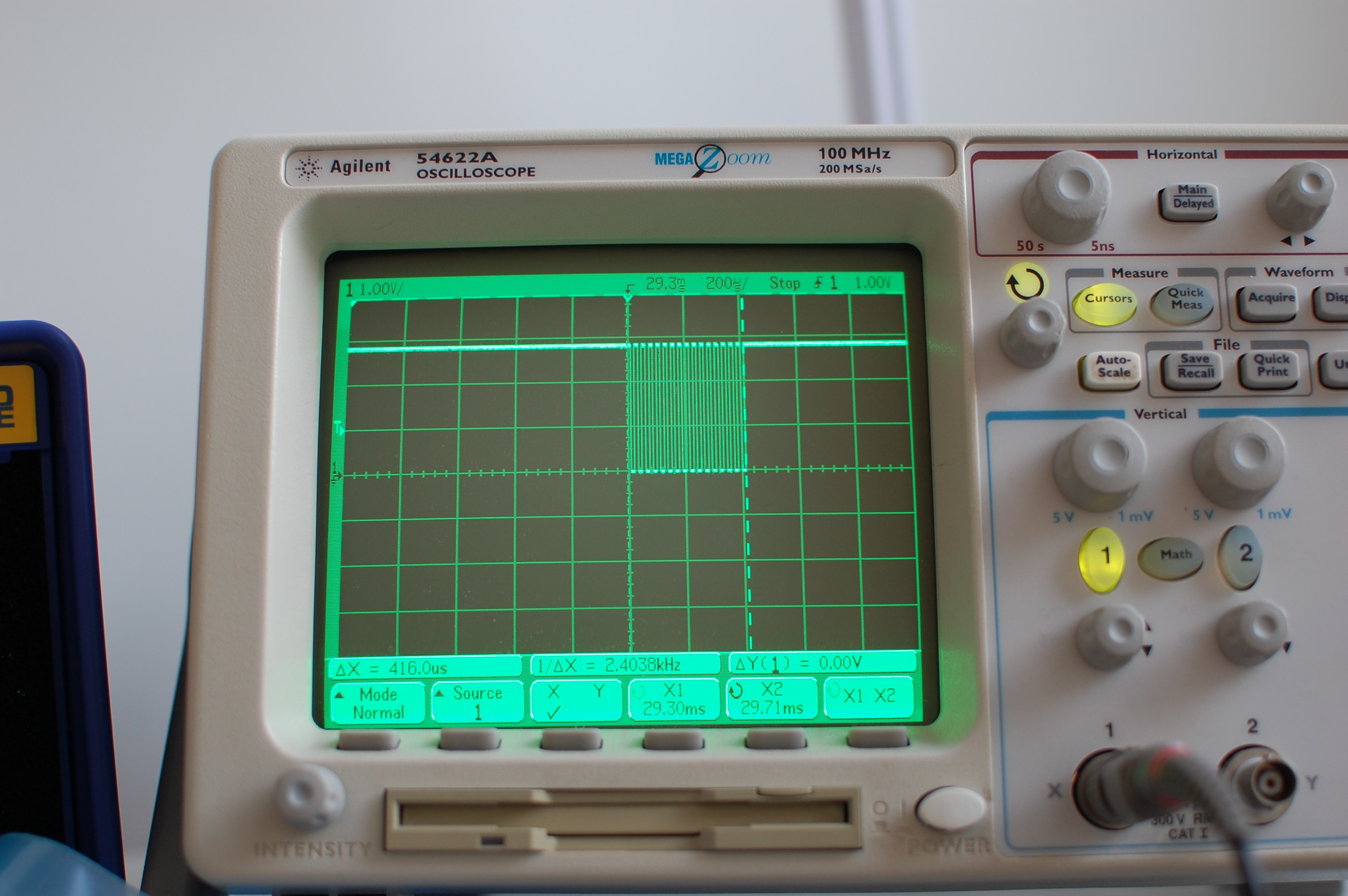
Close up of the 'scope trace for an individual 38 kHz pulse. I had to tweak OCR1x a bit to get the frequency right, which isn't surprising as I'm using the internal RC oscillator.
![]()
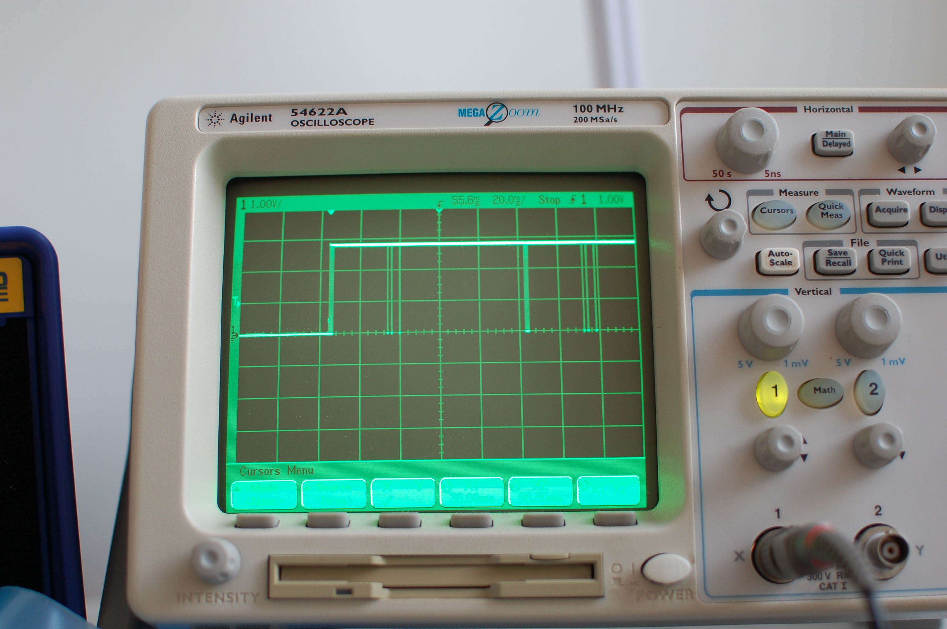
The complete [double] signal; as you can see in the code, after firing the pulses twice the repeat counter shuts off both timers and disables interrupts to be sure. Yes, all the switch does is turn power on to the board; the microcontroller starts up fast enough that it's fine for my purposes, and avoids the need to deal with stuff like sleep mode to save battery life.
![]()
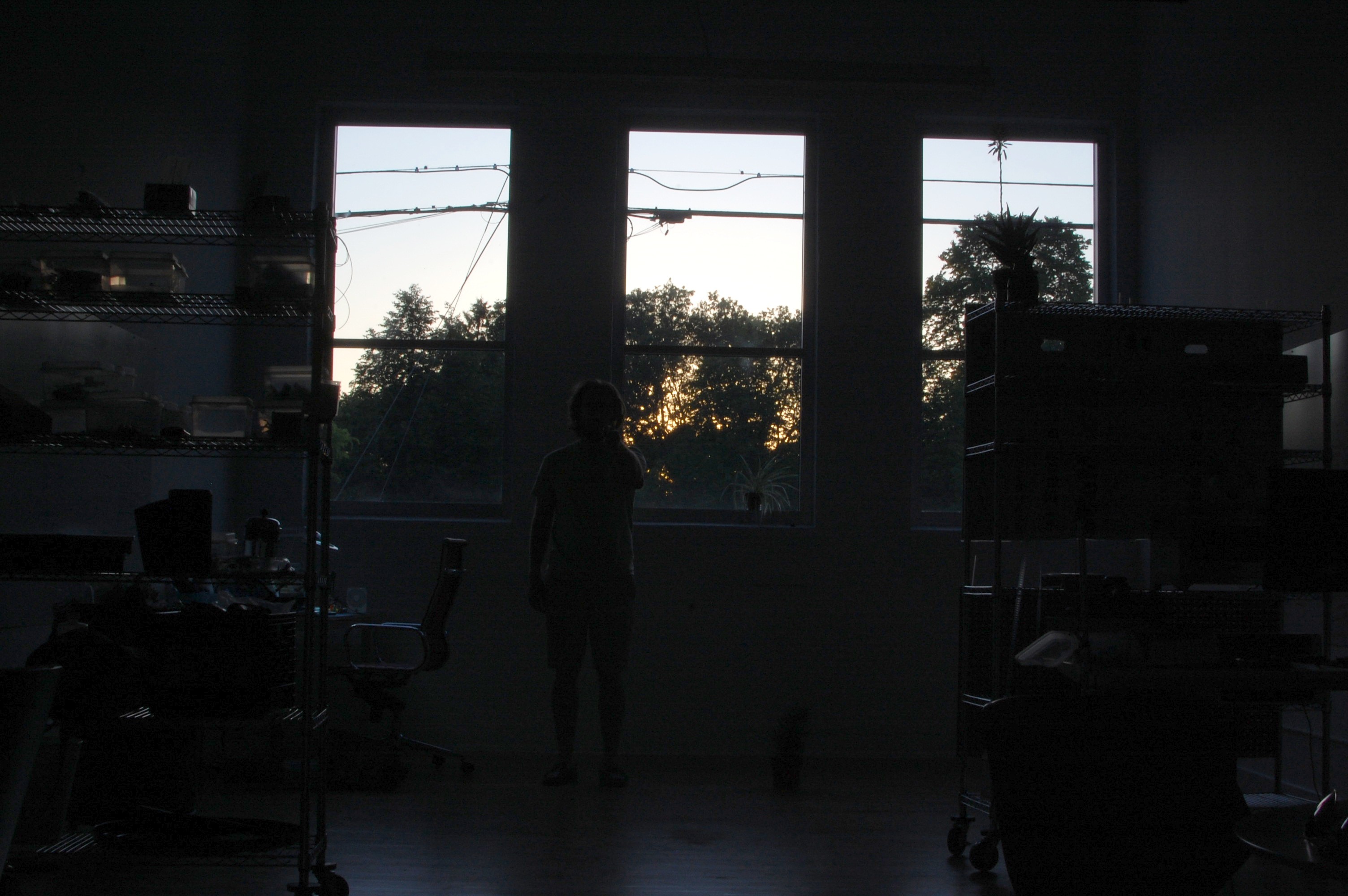
Obligatory first picture taken using the remote! Worked like a charm.
![]()
My office is ~40' long and I wasn't quite up against the wall, so call it a 35' range. This picture turned out at bit funky because my windows face west and the sun was setting.
If you want to build your own, I found Nikon timing specs in a number of places including @limor's intervalometer write-up. She takes the project a step further by building a full timer platform for taking time lapse photos--definitely a worthwhile add-on for a future DIY Nikon remote!
-
mom-timer
12/28/2015 at 03:02 • 0 comments![]()
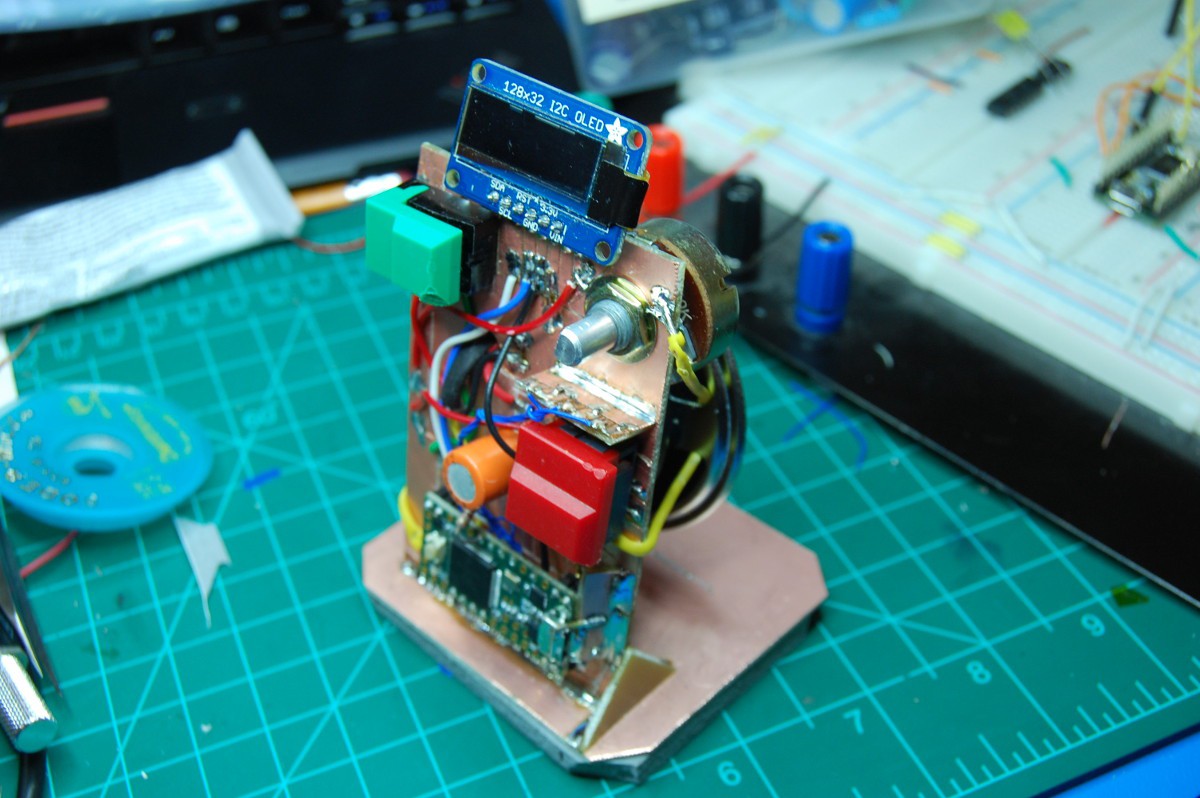
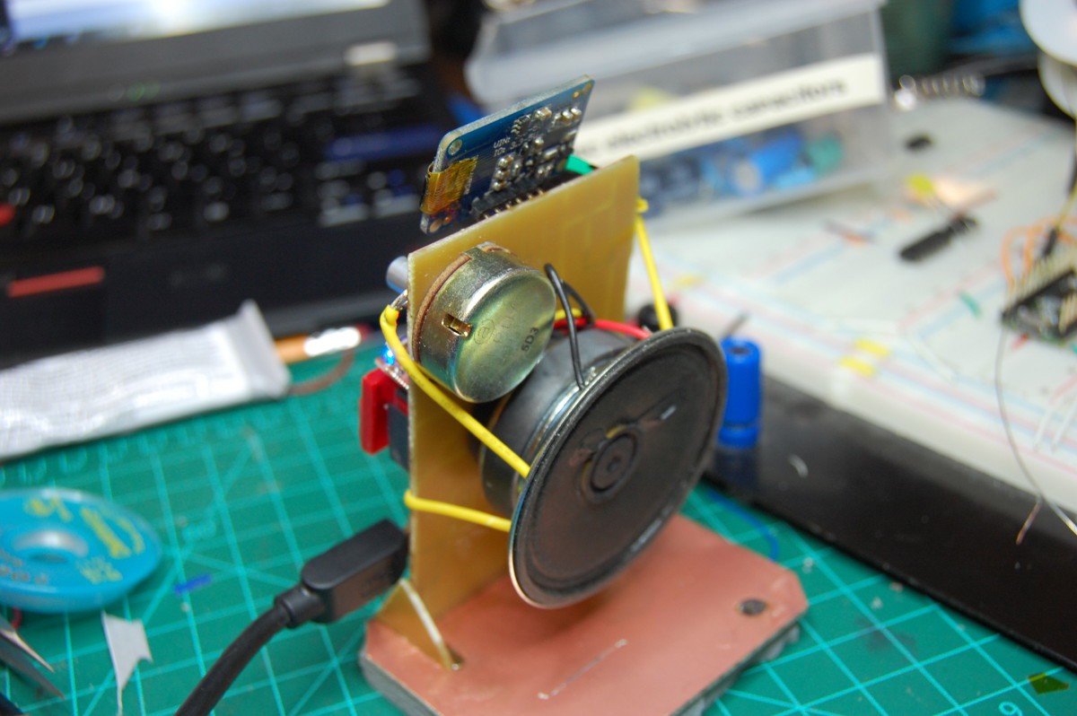
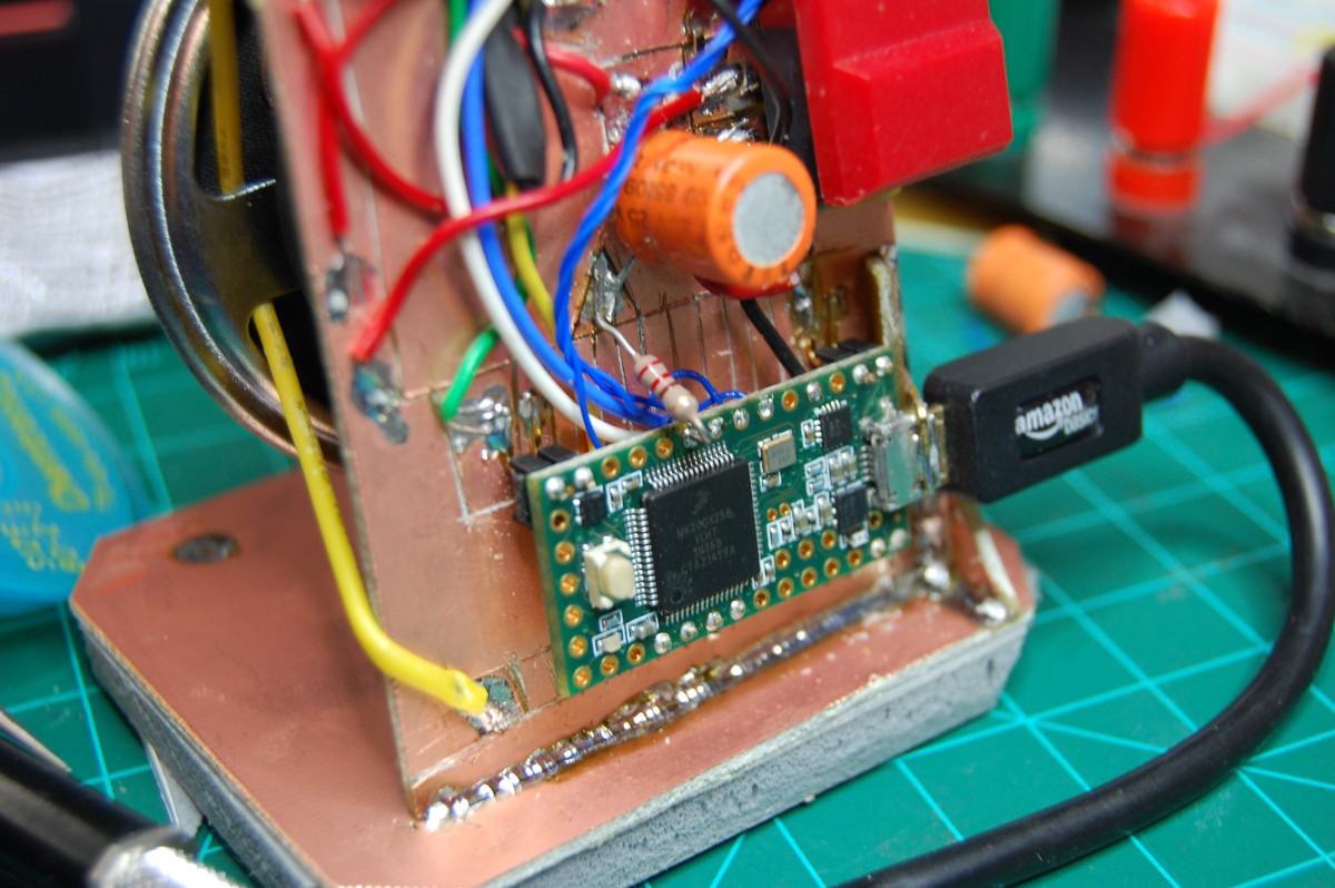
My mom needed a new kitchen timer. I built her one last minute style with stuff I had in my parts drawers. Firmware development was quite hasty (i.e. written on the road) but seems to get the job done. I used a few FR4 scraps to reinforce the Teensy's USB port, as I figured this was the most likely source of breakage (its USB connection is powering the whole deal). I wired the red switch wrong, so it's just for show I guess. Speaker is held in place using a pair of yellow tension wires and a compressed foam pad at its base.
BOM
Teensy 3.2
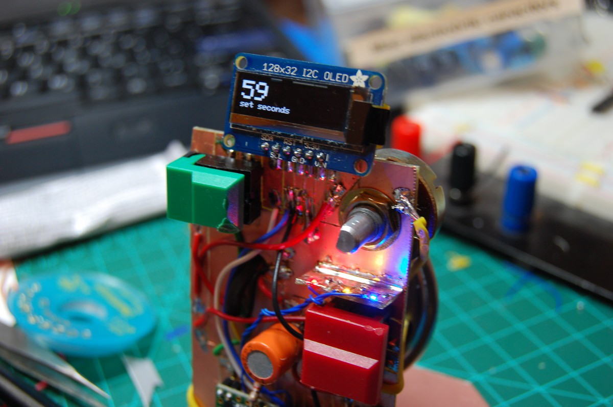
Adafruit 128x32 OLED I2C display
0402 LEDs: 630nm, [some yellowish one]nm, and 470nm
two large switches from a recent surplus haul
10k panel mount potentiometer
8-ohm, 2" paper cone speaker
a large electrolytic capacitor for said speaker
various current-limiting and pulldown resistors
a bunch of 0.062 single-sided FR4
a self-adhesive foam pad
right-angle header to secure the processor board
more pictures
![]()
![]()
![]()
alarm video
A bit of constrained random noise. The function is seeded, so the 'melody' should be identical each time the alarm sounds.
firmware
mom-timer_fw01, as uploaded 12/24/2015. I'm using Adafruit's graphics library along with their drivers for the display, as grabbed from Paul's site. The code includes a rather lengthy instructional intro that mentions the fact that I miswired the red button; as such, the user interface is quite simple. Feel free to ask questions about this, as I probably could add a lot in terms of comments:
note: I didn't add a conclusion to this log update beyond the code block, so feel free to stop here if you're bored [recommended].
/* mom-timer by zach fredin 12-23-2015 my mom needed a kitchen timer, and i needed to get a christmas present for her. this timer is a bit overpowered, but maybe a future firmware update will increase its functionality. it's based on a Teensy 3.2 board, and includes two pushbutton switches, three LEDs, a potentiometer, a speaker, and an Adafruit SSD1306 32x128 I2C OLED display. MIT license for the main function. The two Adafruit libraries are covered by this license which I think I am using correctly in this context: <<< Software License Agreement (BSD License)Copyright (c) 2012, Adafruit Industries All rights reserved. Redistribution and use in source and binary forms, with or without modification, are permitted provided that the following conditions are met: 1. Redistributions of source code must retain the above copyright notice, this list of conditions and the following disclaimer. 2. Redistributions in binary form must reproduce the above copyright notice, this list of conditions and the following disclaimer in the documentation and/or other materials provided with the distribution. 3. Neither the name of the copyright holders nor the names of its contributors may be used to endorse or promote products derived from this software without specific prior written permission. THIS SOFTWARE IS PROVIDED BY THE COPYRIGHT HOLDERS ''AS IS'' AND ANY EXPRESS OR IMPLIED WARRANTIES, INCLUDING, BUT NOT LIMITED TO, THE IMPLIED WARRANTIES OF MERCHANTABILITY AND FITNESS FOR A PARTICULAR PURPOSE ARE DISCLAIMED. IN NO EVENT SHALL THE COPYRIGHT HOLDER BE LIABLE FOR ANY DIRECT, INDIRECT, INCIDENTAL, SPECIAL, EXEMPLARY, OR CONSEQUENTIAL DAMAGES (INCLUDING, BUT NOT LIMITED TO, PROCUREMENT OF SUBSTITUTE GOODS OR SERVICES; LOSS OF USE, DATA, OR PROFITS; OR BUSINESS INTERRUPTION) HOWEVER CAUSED AND ON ANY THEORY OF LIABILITY, WHETHER IN CONTRACT, STRICT LIABILITY, OR TORT (INCLUDING NEGLIGENCE OR OTHERWISE) ARISING IN ANY WAY OUT OF THE USE OF THIS SOFTWARE, EVEN IF ADVISED OF THE POSSIBILITY OF SUCH DAMAGE.
>>> */ #include <SPI.h> #include <Wire.h> #include <Bounce.h> #include <Adafruit_GFX.h> #include <Adafruit_SSD1306.h> #define OLED_RESET 2 #define BUTTON_GREEN 12 //note that, uh, green is low when pressed #define BUTTON_RED 0 #define SPEAKER 7 #define KNOB A2 #define LED_BLUE 4 #define LED_RED 5 #define LED_YELLOW 6 // set up OLED display and button debouncers Adafruit_SSD1306 display(OLED_RESET); Bounce buttonGreen = Bounce(BUTTON_GREEN, 10); Bounce buttonRed = Bounce(BUTTON_RED, 10); // input variables int potState = 0; int potStateScaled = 0; // scales input to 0-59 int buttonStateGreen = 0; int buttonStateGreenPrev = 0; int buttonStateRed = 0; int buttonStateRedPrev = 0; // timer variables int seconds = 0; int minutes = 0; long previousMillis = 0; int LEDflashstate = 0; /* state variables MODE = 0: setup_seconds MODE = 1: setup_minutes MODE = 2: setup_confirm MODE = 3: run MODe = 4: pause MODe = 5: alarm */ int MODE = 0; void setup() { display.begin(SSD1306_SWITCHCAPVCC, 0X3C); pinMode(BUTTON_GREEN, INPUT); pinMode(BUTTON_RED, INPUT); pinMode(KNOB, INPUT); pinMode(SPEAKER, OUTPUT); pinMode(LED_BLUE, OUTPUT); pinMode(LED_RED, OUTPUT); pinMode(LED_YELLOW, OUTPUT); randomSeed(500); // same alarm each time! showIntro(); MODE = 0; } void loop() { unsigned long currentMillis = millis(); getInputState(); if(MODE == 0) { // setup_minutes digitalWrite(LED_BLUE, LOW); digitalWrite(LED_RED, LOW); digitalWrite(LED_YELLOW, LOW); minutes = scaleInput(potState); display.clearDisplay(); display.setTextSize(1); display.setCursor(0,0); display.println("set minutes"); display.setTextSize(2); display.print(minutes); display.println(":__"); display.setTextSize(1); display.println("green to confirm"); display.display(); if ((buttonStateGreen == LOW) & (buttonStateGreenPrev == HIGH)) { MODE += 1; getInputState(); } } if(MODE == 1) { // setup_seconds seconds = scaleInput(potState); display.clearDisplay(); display.setTextSize(1); display.setCursor(0,0); display.println("set seconds"); display.setTextSize(2); display.print(minutes); display.print(":"); display.println(seconds); display.setTextSize(1); display.println("green to confirm"); display.display(); if ((buttonStateGreen == LOW) & (buttonStateGreenPrev == HIGH)) { MODE += 1; getInputState(); } } if(MODE == 2) { // setup_confirm display.clearDisplay(); display.setTextSize(1); display.setCursor(0,0); display.println("timer ready:"); display.setTextSize(2); if (minutes < 10) { display.print("0"); } display.print(minutes); display.print(":"); if (seconds < 10) { display.print("0"); } display.println(seconds); display.setTextSize(1); display.println("green to start!"); display.display(); if ((buttonStateGreen == LOW) & (buttonStateGreenPrev == HIGH)) { MODE += 1; getInputState(); } } if(MODE == 3) { // run if((buttonStateGreen == LOW) & (buttonStateGreenPrev == HIGH)) { MODE += 1; getInputState(); } display.clearDisplay(); display.setTextSize(4); display.setCursor(0,0); if (minutes < 10) { display.print("0"); } display.print(minutes); display.print(":"); if (seconds < 10) { display.print("0"); } display.println(seconds); display.display(); if(currentMillis - previousMillis > 1000) { // "calibrated"... previousMillis = currentMillis; if (seconds % 2 == 0) { digitalWrite(LED_YELLOW, HIGH); } else { digitalWrite(LED_YELLOW, LOW); } if (seconds == 0) { minutes -= 1; seconds = 60; } seconds -= 1; } if((seconds == 0) & (minutes == 0)) { MODE = 5; } } if(MODE == 4) { // pause display.clearDisplay(); display.setTextSize(2); display.setCursor(0,0); if (minutes < 10) { display.print("0"); } display.print(minutes); display.print(":"); if (seconds < 10) { display.print("0"); } display.println(seconds); display.setTextSize(1); display.println("timer is paused!"); display.println("green to unpause."); display.display(); if((buttonStateGreen == LOW) & (buttonStateGreenPrev == HIGH)) { MODE -= 1; getInputState(); } if((buttonStateRed == HIGH) & (buttonStateRedPrev == LOW)) { display.clearDisplay(); display.display(); delay(1000); MODE = 0; getInputState(); } } else if(MODE == 5) { //Alarm mode display.clearDisplay(); display.setTextSize(3); display.setCursor(0,0); display.println("ALARM!"); display.setTextSize(1); display.println("green to reset."); display.display(); if(currentMillis - previousMillis > 200) { previousMillis = currentMillis; if (LEDflashstate == 0) { digitalWrite(LED_BLUE, HIGH); digitalWrite(LED_RED, LOW); LEDflashstate = 1; tone(SPEAKER, random(200, 600), 200); } else { digitalWrite(LED_BLUE, LOW); digitalWrite(LED_RED, HIGH); LEDflashstate = 0; tone(SPEAKER, random(600, 1800), 200); } } if((buttonStateGreen == LOW) & (buttonStateRedPrev == HIGH)) { display.clearDisplay(); display.display(); delay(1000); MODE = 0; getInputState(); } } } int scaleInput(int rawValue) { // okay, so this cuts out ~10% of the pot's range.. oh well, bitshifts are the best. if(rawValue < 960) { return rawValue >> 4; } else { return 59; } } void getInputState() { // store previous button values buttonStateGreenPrev = buttonStateGreen; buttonStateRedPrev = buttonStateRed; // update button and knob values buttonGreen.update(); buttonRed.update(); potState = analogRead(KNOB); buttonStateGreen = buttonGreen.read(); buttonStateRed = buttonRed.read(); } void showIntro() { // splash screen and operating instructions (includes delays) display.clearDisplay(); display.setTextSize(2); display.setTextColor(WHITE); display.setCursor(0,0); display.println("mom-timer"); display.setTextSize(1); display.println("firmware v0.1"); display.println("merry xmas, mom"); display.display(); tone(SPEAKER, 440, 100); digitalWrite(LED_BLUE, HIGH); delay(3000); display.clearDisplay(); digitalWrite(LED_BLUE, LOW); display.setCursor(0,0); display.println("TIMER SETUP MODE"); display.println("set time with knob."); display.println("green to confirm"); display.println("and start countdown."); display.display(); tone(SPEAKER, 440, 100); digitalWrite(LED_YELLOW, HIGH); delay(3000); display.clearDisplay(); digitalWrite(LED_YELLOW, LOW); display.setCursor(0,0); display.println("TIMER RUN MODE"); display.println("green button pauses"); display.println("and resets. red"); display.println("button was miswired."); display.display(); tone(SPEAKER, 440, 100); digitalWrite(LED_RED, HIGH); delay(3000); display.clearDisplay(); digitalWrite(LED_RED, LOW); } -
Single 7-segment POV display
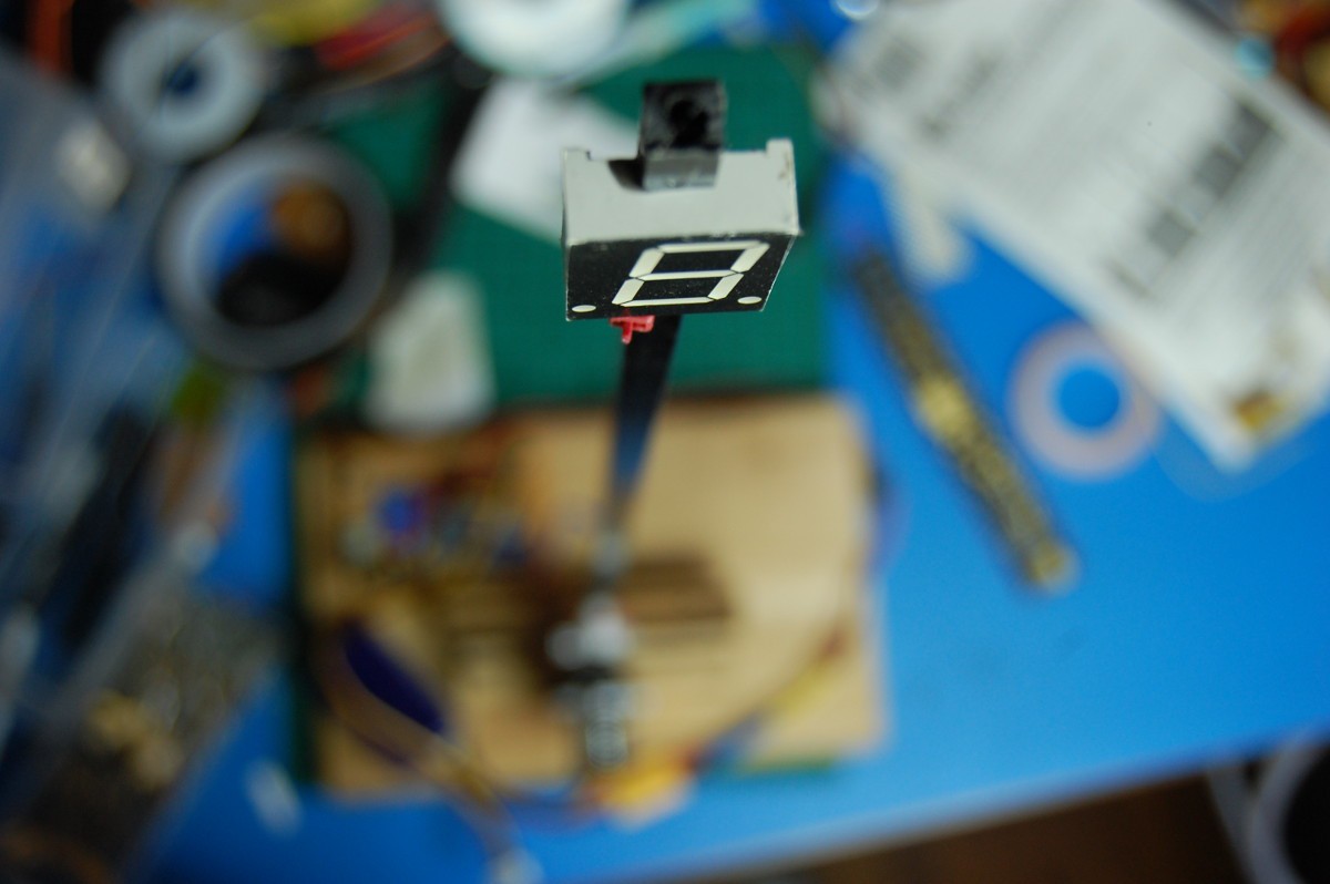
10/22/2015 at 15:53 • 0 commentsI wanted to build a clock, or something like a clock, but then I only had one 7-segment display lying around (purchased surplus, probably 15 years ago). Luckily, I also had a pretty beefy high-speed servo, some mechanical parts, a length of square pulltruded CFRP rod, and a handful of electronic bits as well. No RTC functionality, so right now it emulates a group of 7th graders that just figured out how to spell "naughty words" on their calculator screens:
The rapid servo acceleration causes the whole thing to jump about on the workbench, which could probably be solved by additional weight and/or foam padding but is pretty hilarious to watch. The firmware, running on one of many Pro Minis I had lying around, is so half-assed that I don't think I actually saved the file after uploading it. As you can imagine, it makes liberal use of really basic Arduino functions like digitalWrite and the servo library.
More pictures.
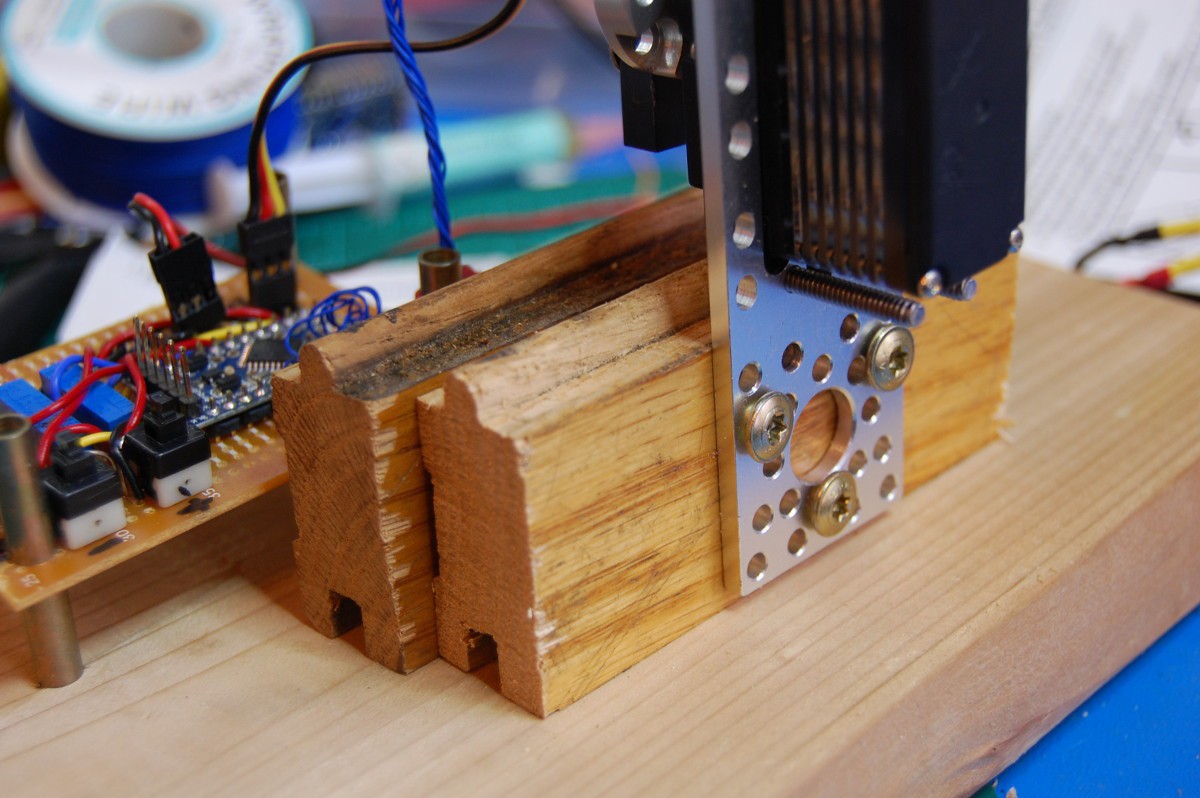
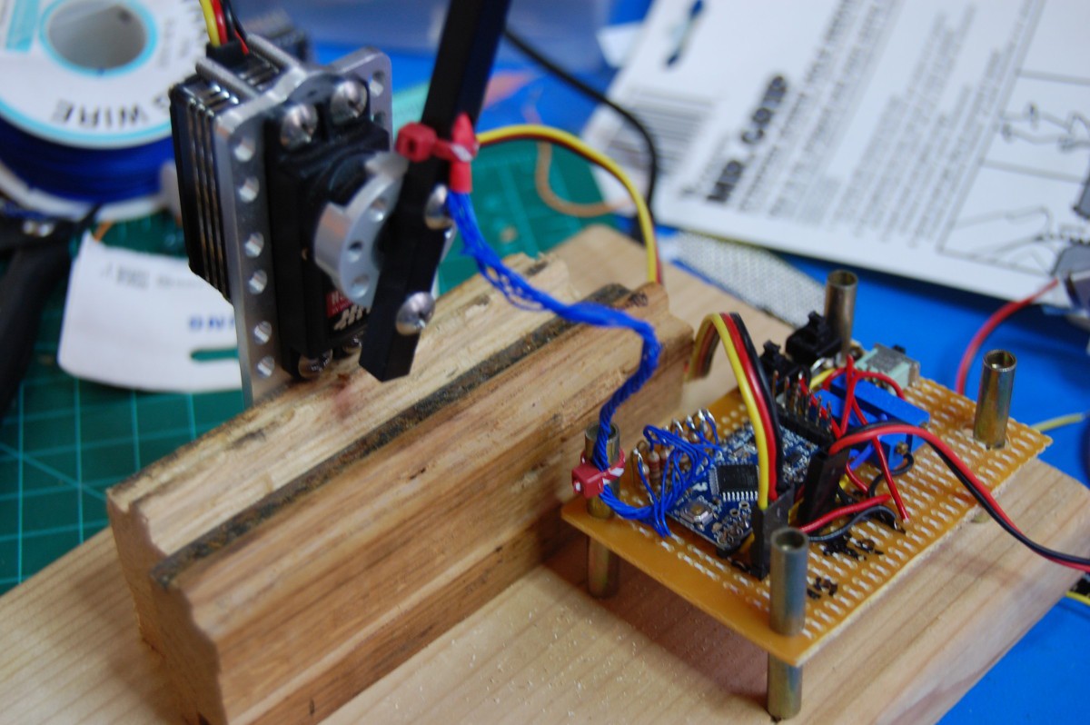
Servo mount--some Actobotics bits (along with the servo itself) from #GimbalBot, taken out on long term loan from that project. Also shown: a few chunks of oak flooring I ripped up from my second floor. Don't worry, most of it is still installed and awaiting refinishing (ETA: 2040):
Front view of the mounted servo, showing the eight wires (7 + gnd) that feed the display. Yup, they're wire-wrap solid core wires--probably not the best fatigue life in this application, but I don't run the display much since (as mentioned above) it tends to walk off the desk:![]()
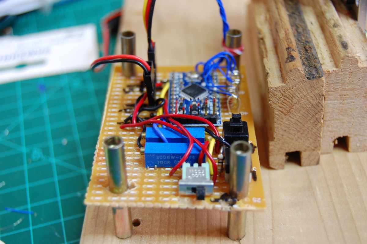
![]() Board detail, featuring seven identical current limiting resistors and a few switches and pots I had lying around. Right now the power switch is the only functional "user interface"; I intended to use the trimmers to adjust things like letter spacing and speed on the fly, while the buttons would change the message. We'll see if that ever actually happens:
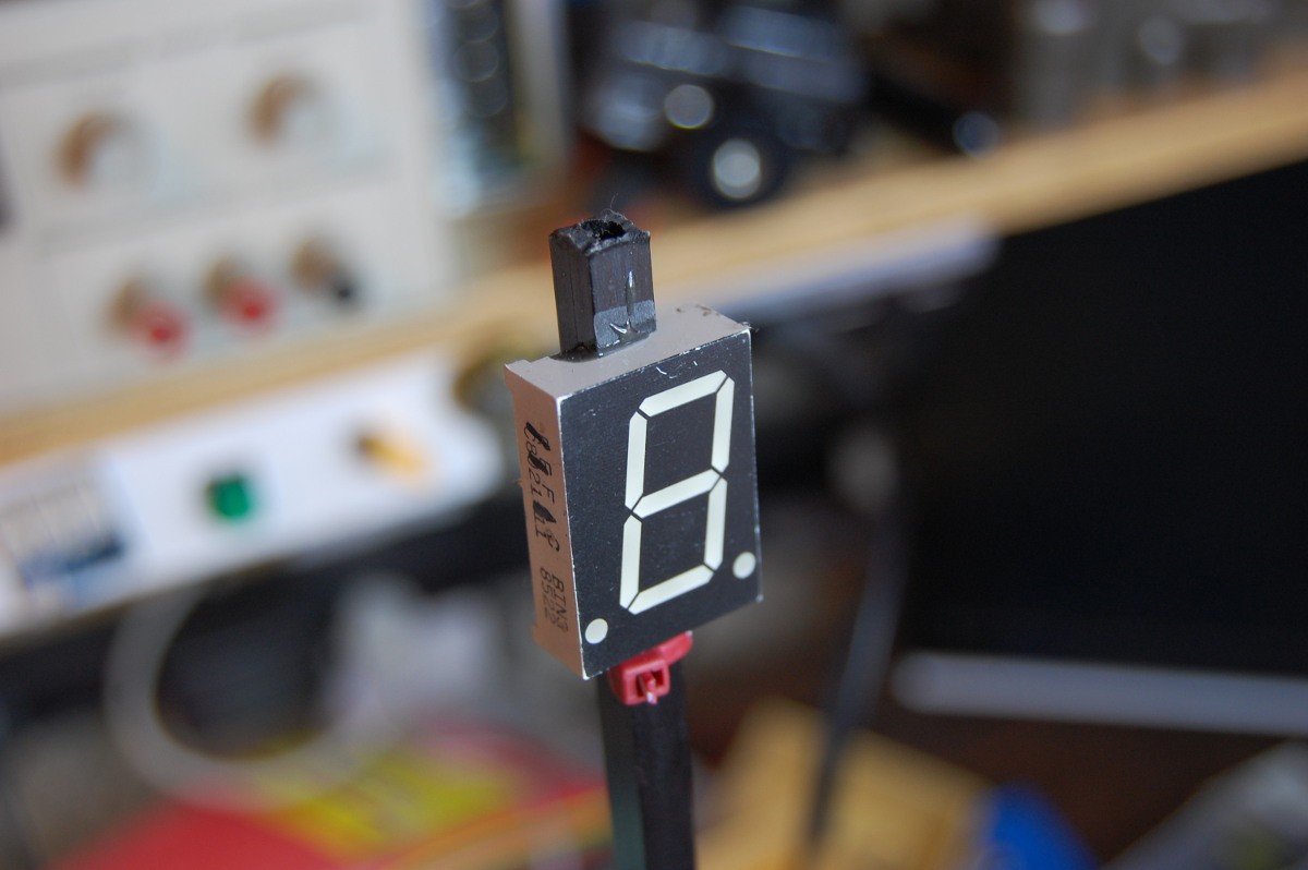
Board detail, featuring seven identical current limiting resistors and a few switches and pots I had lying around. Right now the power switch is the only functional "user interface"; I intended to use the trimmers to adjust things like letter spacing and speed on the fly, while the buttons would change the message. We'll see if that ever actually happens:![]() Front view of the single 7-segment display. I didn't wire up the decimal points:
Front view of the single 7-segment display. I didn't wire up the decimal points:![]() Top view of the display, mostly out of focus, showing the CFRP tube profile. The tube itself was notched with a diamond-tipped Dremel bit, then JB-welded in place. So yeah, it was a Saturday-Sunday type of project, since the epoxy had to set up:
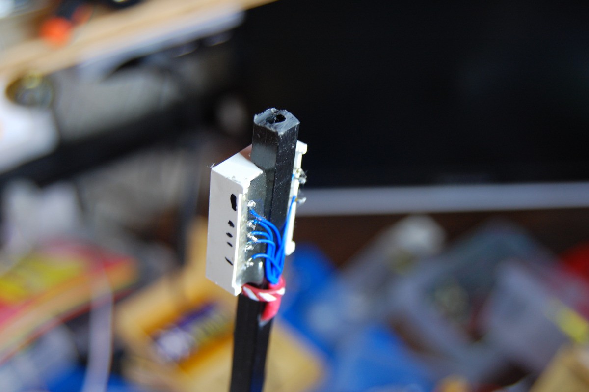
Top view of the display, mostly out of focus, showing the CFRP tube profile. The tube itself was notched with a diamond-tipped Dremel bit, then JB-welded in place. So yeah, it was a Saturday-Sunday type of project, since the epoxy had to set up:![]() Rear view of the display, showing the connections (along with marks from initially determining which leads powered which segments). You can see that I pretty thoroughly notched the CFRP tube and was pretty liberal with the JB weld application. The wires are heat-shrunk together where they enter (and exit) the tube in an attempt to mitigate potential abrasion damage to the insulation:
Rear view of the display, showing the connections (along with marks from initially determining which leads powered which segments). You can see that I pretty thoroughly notched the CFRP tube and was pretty liberal with the JB weld application. The wires are heat-shrunk together where they enter (and exit) the tube in an attempt to mitigate potential abrasion damage to the insulation:![]()
weekend novelty projects
minimal advanced planning. built from stuff i already have around the shop. typically not very useful. generally completed in one weekend.