Since I do this project on free time it is important that I could put it away without taking a lot of space. So decided to make the control panel smaller. And it should help out for people that has these printers with failed control panels (have seen a few of those).
Functions needed on a new panel:
1. Power-on button
2. Power LED (indicates possible errors)
3. Error LED (indicates possible errors)
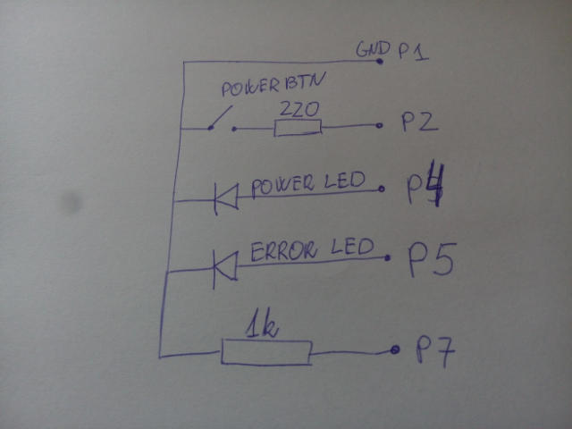
The schematic is fairly straightforward. I used the components from the original control panel and put them on a small peace of veriboard.
Pin 1 - GND
Pin 2 - Power-On button
Pin 4 - Power LED
Pin 5 - Error LED
Pin 7 - Panel Sense? (does not work without this one).
Power-ON button connects ground to the main controller via 220 Ohm resistor. And Pin 7 should be connected to GND via 1K Ohm resistor. LEDs are controller via positive voltage. Pin 1 is the top one of the ribbon at the main controller board (other way around than the silkscreen on the PCB (noticed that too late)).
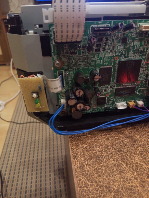
After some soldering and hot glue, it does work like treat.
Just a reminder that this is for Canon MP210, but the panel are pretty much the same on all cheap MP series printers of the same generation.
How it looks right now:
Discussions
Become a Hackaday.io Member
Create an account to leave a comment. Already have an account? Log In.