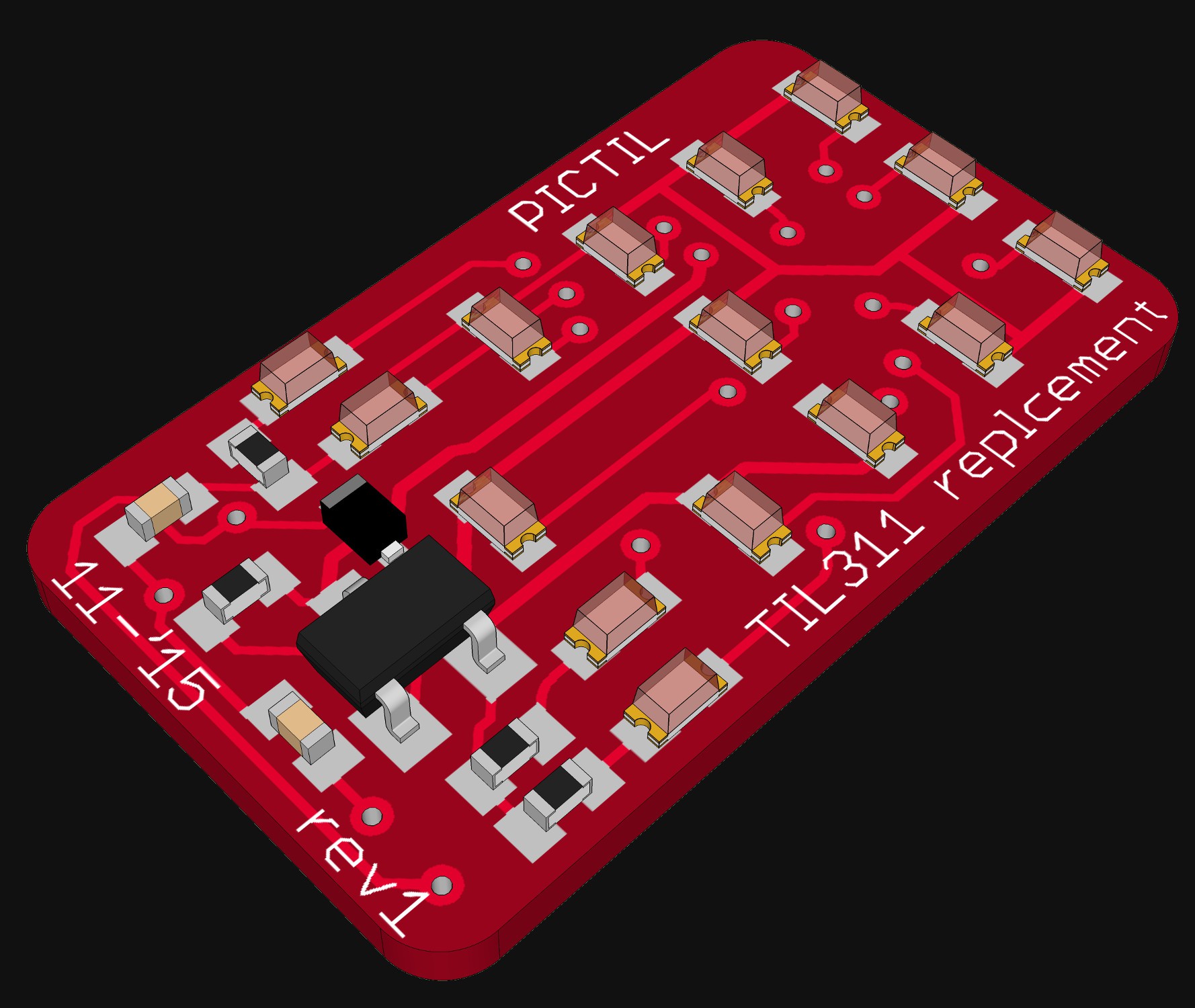
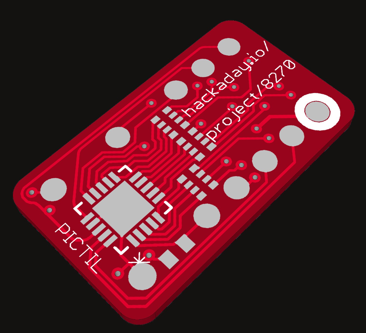
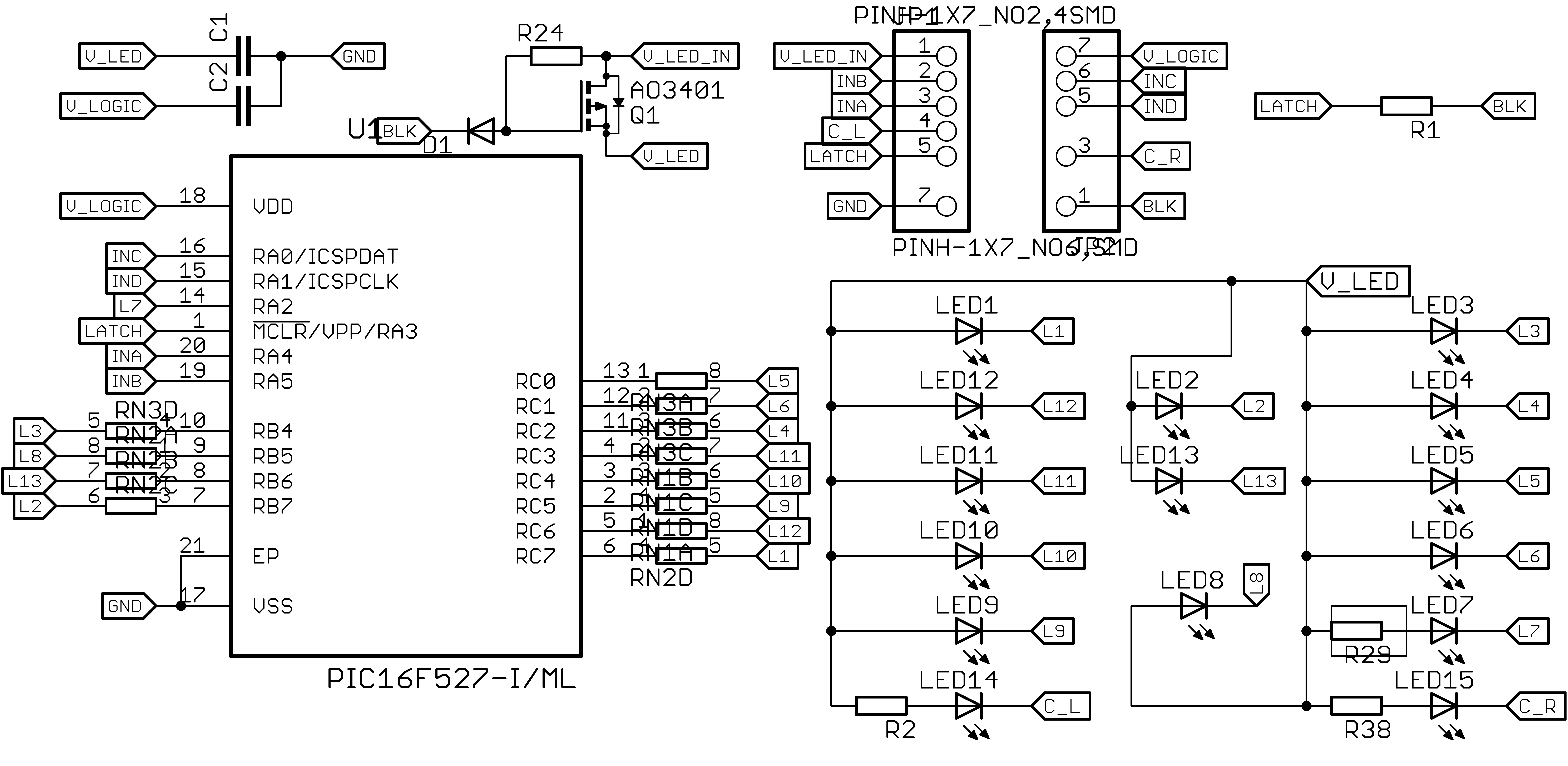
The comments on the last log were good. Thinks I changed:
- resistor Arrays
- resistors on the back
- diode at the gate ( I hope right)
- switched to 0603 LEDs (resistors and capacitors are still 0402)
So here are some pictures as an update:


A project log for PICTIL
Remake of the TIL311 hex LED display with recent technology.
The comments on the last log were good. Thinks I changed:
So here are some pictures as an update:


Discussions
Become a Hackaday.io Member
Create an account to leave a comment. Already have an account? Log In.
Nice work :) Considering a black solder mask for maximum contrast?
Are you sure? yes | no
Thank you!
I will consider black solder mask later. In the rendering I used red to get them look more like the original TIL311. The first prototypes will be purple (OSH-Park).
Are you sure? yes | no
If you're clever with your software, you could probably get away with a single resistor for all the LEDs and save some tiny-soldering ;)
Are you sure? yes | no
mh.. the only way I could imagine to reduce the number of resistors is to use some multiplexing.
What do you have in mind?
Are you sure? yes | no
just scan through 'em... only one LED is on at a time, but done so quickly there's no noticeable flicker. With the brightness of LEDs these days, and their often being rated for brief pulse-currents much higher than their constant-current rating... Definitely more work, software-wise, but once it's done it's done...
Erm, of course, the PIC will have to be able to source that much current on each of its pins... keep that in mind. Maybe group them in groups of four and use 3 resistors, etc.
Are you sure? yes | no
PIC pins are rated at "25mA" so there should not be a problem on this side. If you run 1mA per LED, you'll have 20mA through the ground pin (that's fine) and more than enough light.
If you turn each LED one by one, use Charlieplexing instead of direct drive : this will save pins and a cheaper PIC with less pins will work.
Charlieplexing works great for 20 LED because 20=4×5=n²+n, so you need only 5 bidirectional pins. I've done this on a 8-pins PIC16F for another application, it's maybe a bit tricky in the beginning but that's not black magic.
Are you sure? yes | no
Note : Charlieplexing also reduces the number of resistors. There would be one 100 ohms per pin, because to turn a LED on, the current passes through 2 pins (2 resistors) plus the (small) resistance of the IO pin.
This also removes the FET/diode/pull-up because "blank" would be a freeze of the CPU. And Vled would not be used...
Are you sure? yes | no
Wow ! Slowly but surely, it's getting amazinger ! ;-)
The last PNG is black, is it an error ?
I still believe you could put two 0603 LEDs in parallel for the segments (even sharing the same resistor).
I'm not sure it qualifies for https://hackaday.io/project/7813-the-square-inch-project but if it does, you should enter your design :-)
Are you sure? yes | no
Your design does ! The original TIL311 is 19.31×10.67mm, well under the 25.4mm limits.
Are you sure? yes | no
Yes the black was an error - I fixed that
I could only use two LEDs for some segments (all the "long" / non corner ones) and these than would need an different resistor value. This would be problematic with the resistor arrays.
Are you sure? yes | no
My hypothesis is that it does not matter that much. The eye will only see a tiny change, which will be imperceptible with small resistor values. What value did you plan ? I'd shoot for 100 Ohms and favor low power :-)
Are you sure? yes | no
If powering it from 5V I would use >100 Ohms. Some LEDs are very bright. Sometimes I use 1K. So I would test 470, 680, 1K. Depending on color and supply voltage.
Are you sure? yes | no
At 5V the TIL311 burns a lot of power so it's wise to reduce the Vled. I drop to 3.5 and it still gets warm.
If you consider a 5V supply then the two red LED would be in series, like in the original.
Are you sure? yes | no