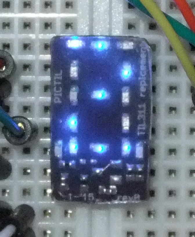
While building a second board I did noticed some issue.
- There is I mistake in the schematic and because of that also on the circuit board. I should had noticed that before but source and drain are interchanged.
This can be fixed by not using the blank-circuit and bridging the transistor by a 0 Ohm resistor (like in picture posted before). - The mounting of the pins is mechanical very weak. I did have a lot of trouble with with it.
There is no good workaround for this just be careful and/or use some hot glue.
The second board is with blue leds. And I did also experiment a little bit with molding the whole module with hot glue. I will take some pictures soon and write about this in a next log. Here is a "spoiler" picture:
 Alex
Alex
Discussions
Become a Hackaday.io Member
Create an account to leave a comment. Already have an account? Log In.
It can only get better ;-)
Are you sure? yes | no