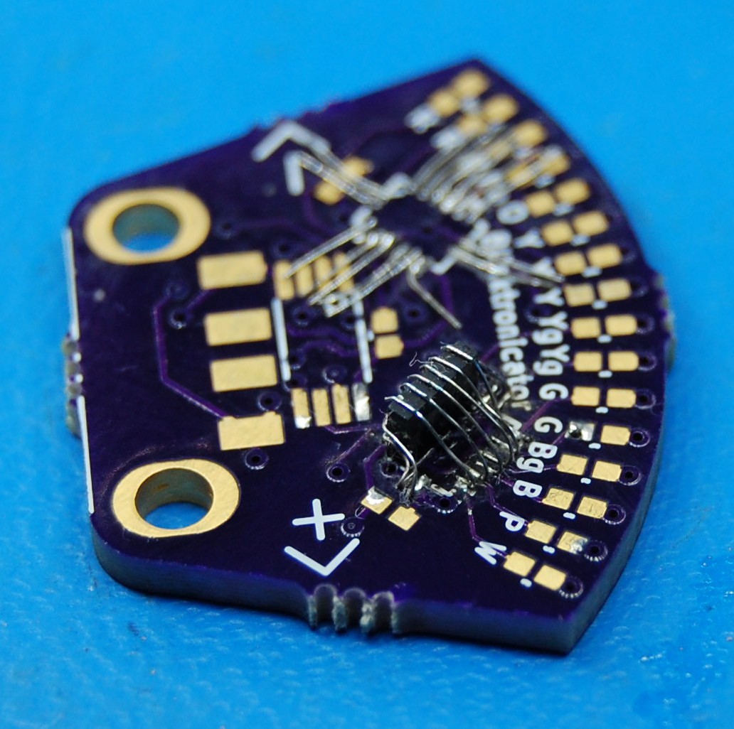
As suggested in the video from the last log, I finished soldering together one of the bad boards. Today, I took a bit of @K.C. Lee's advice and tried standing the shift registers up on one edge:

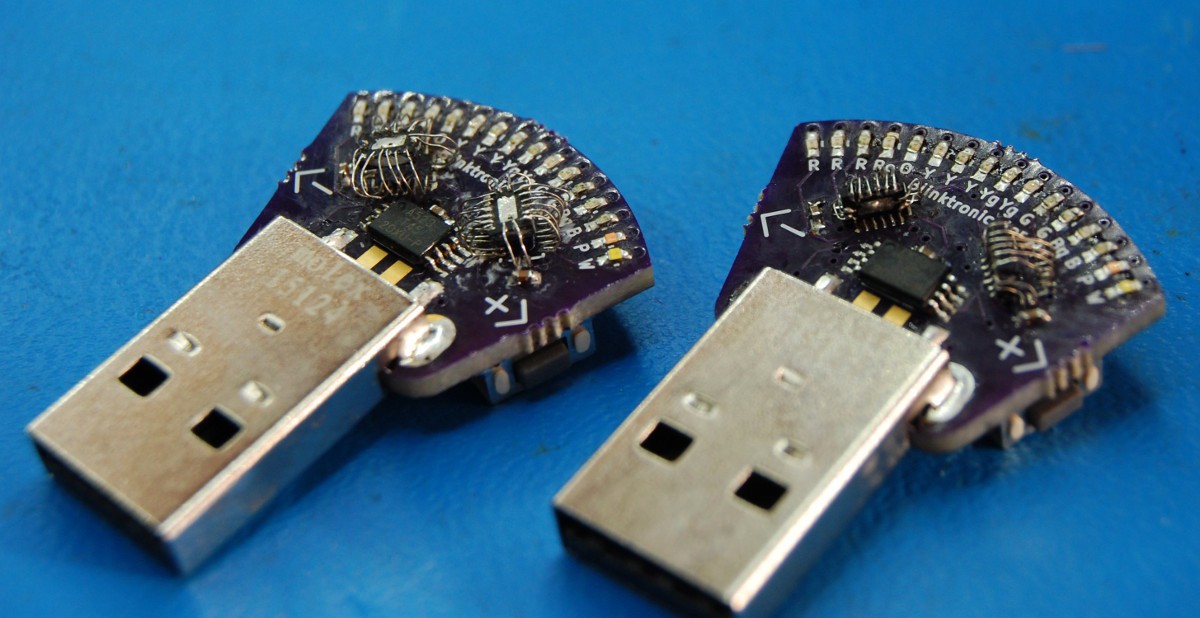
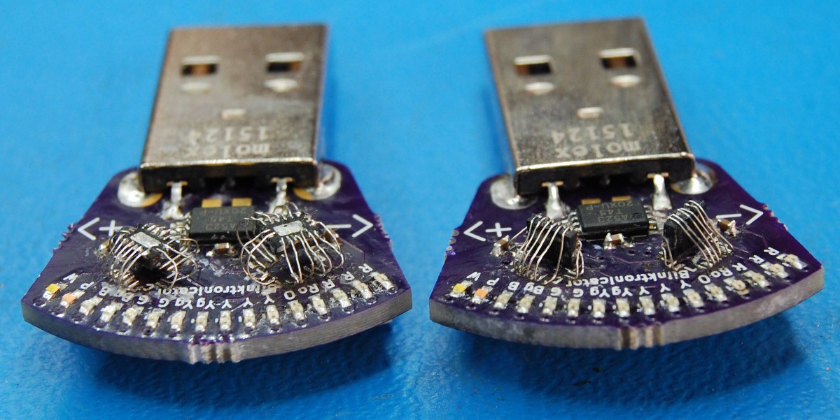
After some de-fluxing, this is what the two boards look like side-by-side:
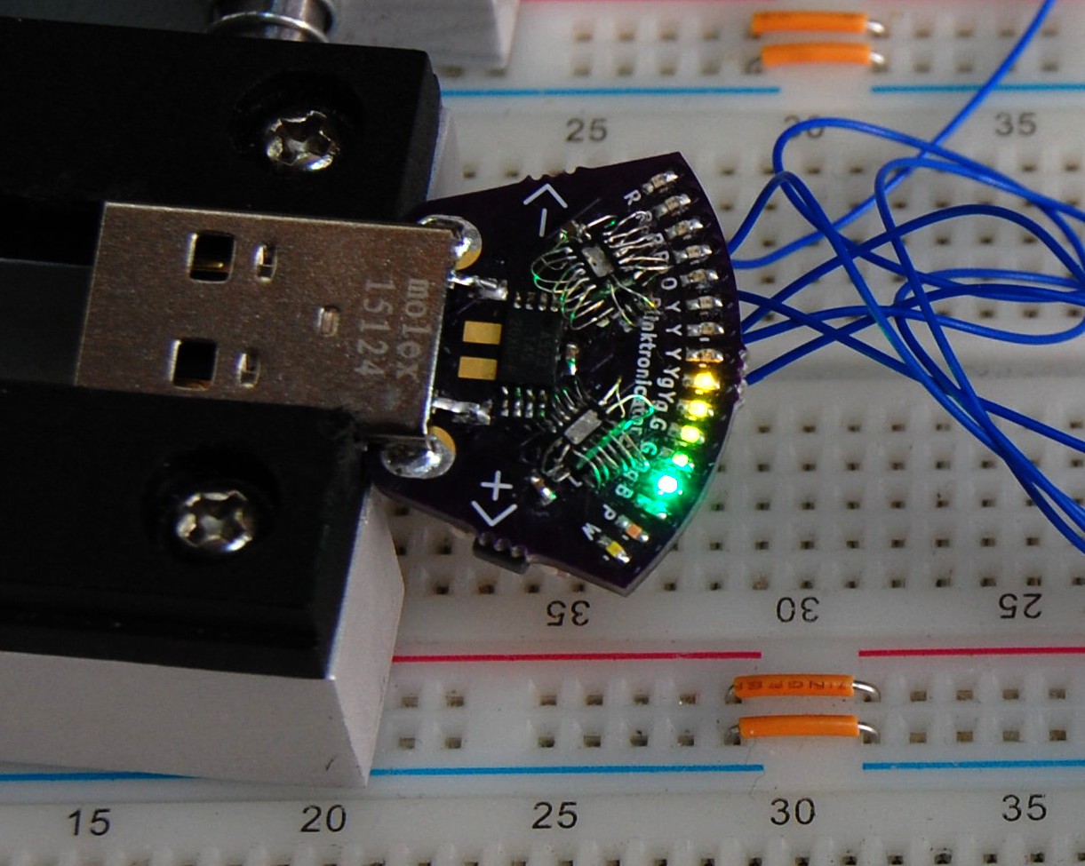
I also temporarily soldered wires onto the six programming pads of the first board and tapped the board a few times to re-check the LEDs (the newer board was checked in a USB hub):
So why the '-ish' in the post title? Well... I haven't actually tested the functionality of the boards. As in, I haven't sent the shift register a specific series of pulses and observed the correct result.
The second '(-ish)' in the title is because this hardware iteration is destined for the wastebasket: it requires the user to install 67% of the ICs upside-down. Not a good design! I did update the schematic and board layout but haven't double-checked the work yet; I want to be sure I include some of the other complaints I'd recognized previously. And I want to make sure the circuit works, so that means the next step is [finally] working on firmware using the two existing prototypes.
 zakqwy


Discussions
Become a Hackaday.io Member
Create an account to leave a comment. Already have an account? Log In.
You've got 23 more hours. You should be fine. ;)
Are you sure? yes | no
Ah, but I am code-challenged ;-)
Are you sure? yes | no
You just need to demonstrate your hardware works. A line going from one end of the board to the other would suffice ;)
Are you sure? yes | no
Okay, I just got to that point--if I make no more progress tonight I will post that picture..
Are you sure? yes | no