-
USB power. Boards ordered.
12/08/2015 at 05:22 • 2 comments[update 12/8/2015, part 2: OSHpark cancelled the previous board and swapped the new ones in their place. Just got all the parts on order--the blue units were backordered so I found 'em via a different supplier. I ordered .. uh .. a lot of LEDs. More than I need for this project. Any ideas... ?]
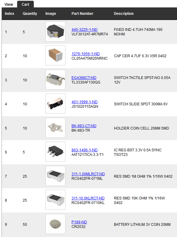
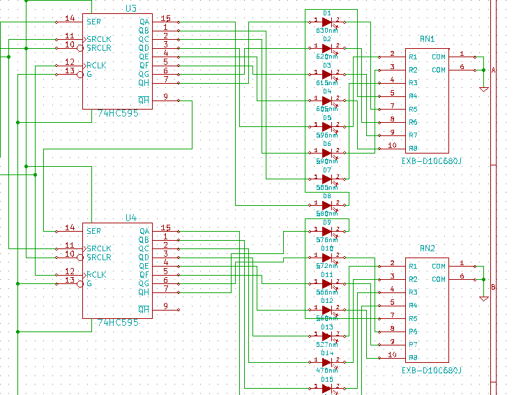
[update 12/8/2015: I realized when I was updating the BOM that the resistor networks were sized for a 3.3vdc power supply. Unfortunately, due to voltage drop/current draw requirements, moving to direct USB power (5vdc) means I need larger resistor values for the InGaN units (four total). So I updated the schematic and PCB this morning and sent a panicked note off to OSHpark; with any luck I'll be able to squeeze the new design into their production queue. Either way, the GitHub repo is now correct.]
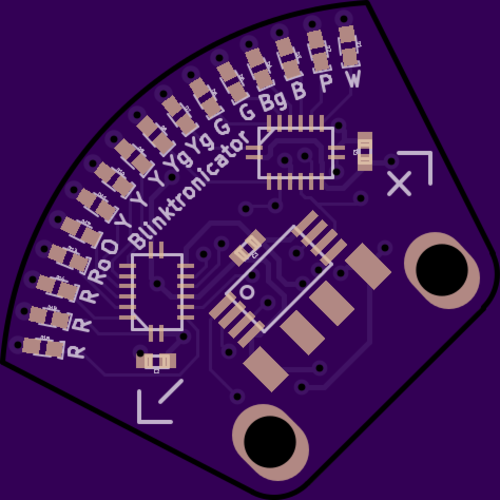
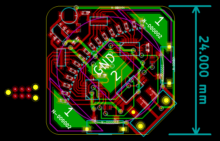
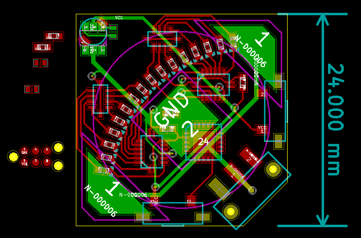
It got a bit tight around the ICs. We'll see how this shakes out. The USB connector pads are hilariously large compared to everything else. I hear OSHpark does slots now, but I opted to use 2.5mm holes for the structural bits.
No room for wavelength designations on the front, unfortunately...
![]()
![]()
![]()
My apologies to all for dropping the ball with respect to symmetry--the two pulldowns on the back are embarrassingly unmatched. But at some point, you just have to call it good enough.
I think I still have a few things to do to comply with the contest (BOM, etc)--I'll also get the latest files into the github repo.
-
More tests, changes, etc.
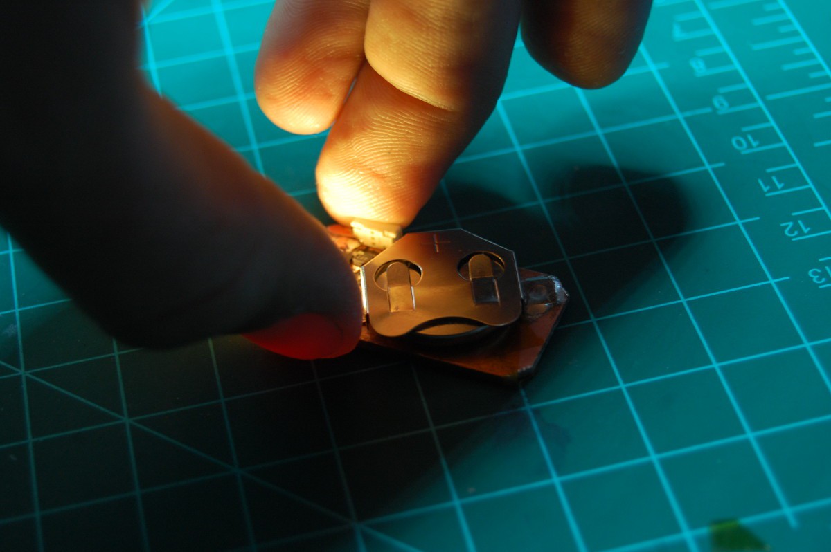
11/17/2015 at 23:42 • 3 commentsNews flash: the three LEDs dimmed pretty quickly. I could look at them without blinking a lot within 15 minutes or so. They did stay noticeably lit for a long time though--barely enough to navigate with through a dark room, but still pretty impressive. The battery was getting dragged down below 0.5vdc and the output also sagged a lot, so I eventually decided to desolder two of the parallel LEDs. Then, before I could do much else, I decided to make the board into a keychain, so I coated all of the exposed copper with a few layers of clear nail polish and added a soldered on hook. Makes a great accessory for a loupe, I suppose:
Anyhoo, encasing everything in clear nail polish also made it hard to measure the voltage drop across the current limiting resistor (for example), and I got tired of digging the volt meter probe under the battery to get a value there. Either way, this circuit served it's main purpose--it taught me that Building Boost Converter Circuits Is Possible.
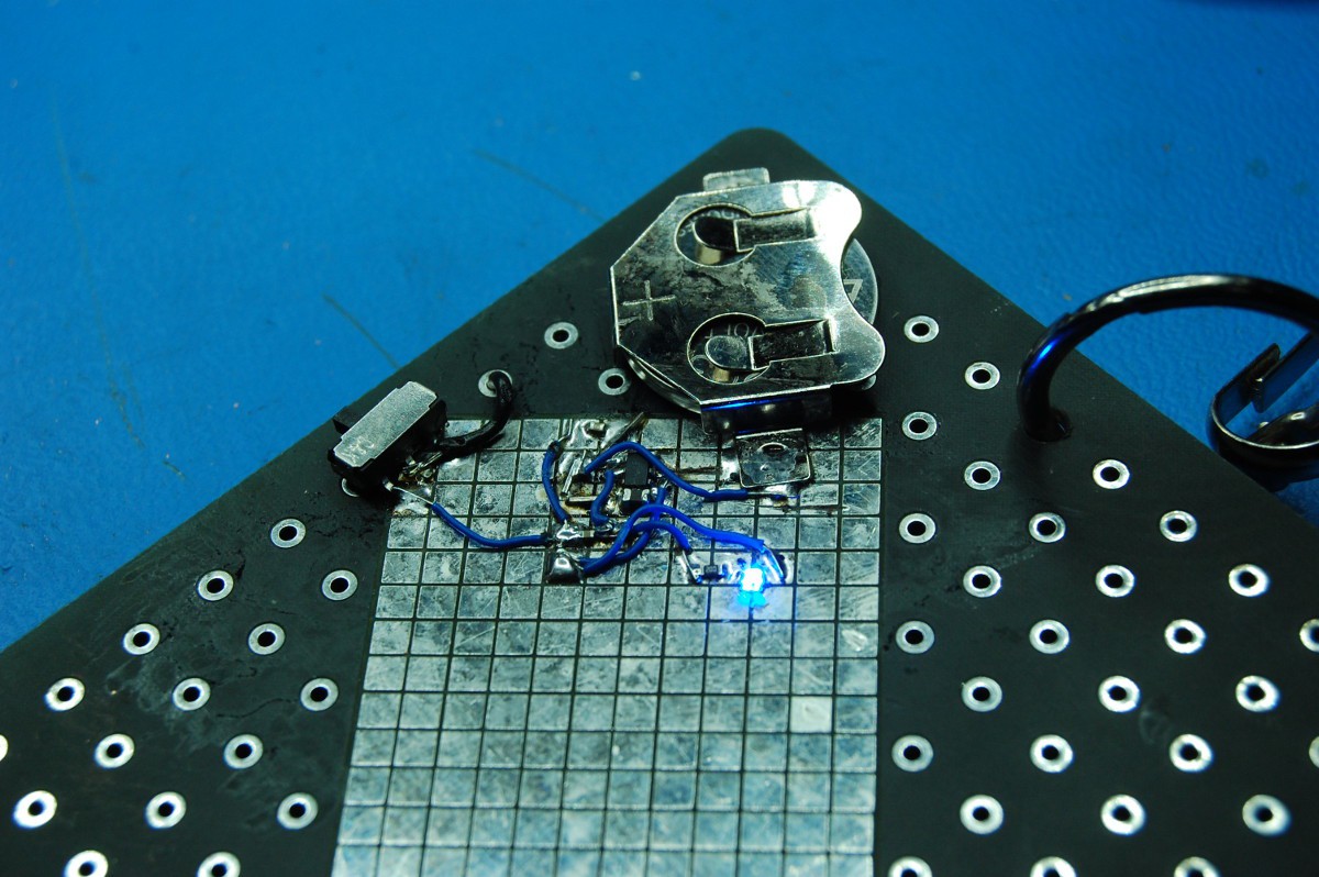
At the [excellent and amazing] Hackaday Superconference, I used a bit of the prototyping area on the rear of my badge to recreate the circuit with a few changes:
- a blue LED (well, half of a blue/red LED) yanked from #NeuroBytes' v05 prototype stash
- a 20 ohm current limiting resistor for said LED
- a slide switch for permanent "on" operation
- less [no] nail polish
- swapped inductors to the cheaper style
Still required a few trace cuts, as the standard pads were a bit wide. Ironically, I also had to sloppily lengthen some using scraps of wire since so many parts connect to the IC. After determining that it didn't work because I'd (a) forgotten to wire up the battery positive terminal, and (b) the LED was installed backwards (who puts their green dot on the cathode??), the badge powered up (shown here de-fluxed after I got home):
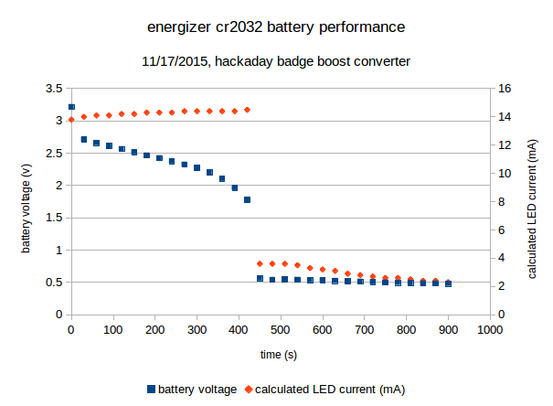
Beyond taking some (many) continuity measurements during soldering, I didn't test things like battery voltage sag and LED current in SF. I did notice that the LED wasn't nearly as bright after a few hours of constant "on" operation, and eventually had trouble staying lit (although I could give the battery some recovery time and it usually powered on after that).Back in Mpls, it's time for some poorly instrumented tests with a fresh battery, a phone-based timer, and a voltmeter. Results, with LED current calculated based on voltage drop across the current limiting resistor:
![]()
yup, the coin cell pretty much crashed around the 4 minute mark, although the battery voltage curve is probably pretty smooth (just steep) at the "cliff". My data acquisition rate was 2 samples/minute with a fairly sizable lag between the two values, since I'm using the same multimeter for both.
Either way, it's a problem for the Blinktronicator--while the boost converter clearly works, even with a single LED driven at ~70% of its datasheet spec the circuit pulls the coin cell too low to really function. It's nice that the LED stays lit for a long time after the crash, but it's not too bright at ~2mA.
So.. more experimentation to do. I should probably wire in taps so I can chart current into the circuit and at least see how efficiently it's operating. At some point, it might make sense to just make the thing externally powered, huh?
-
Parts arrived, needed to test
11/11/2015 at 21:41 • 1 commentI had a package waiting when I got home, so I put together a simple test circuit using an extra piece of copper clad board. It's basically the power supply circuit portion of this project with a momentary switch, a dropping resistor, and three white LEDs in parallel. I had to add a bit of kapton tape under the battery as I hadn't taken out enough copper and I was getting a short circuit:
The LEDs are pretty bright, so this is the best action shot I could get:
I checked--the battery voltage sags to around 2.2 vdc when I hit the button (and dropping...); however, the output rail is steady at 3.3 vdc. Voltage drop across the resistor suggests the LEDs are pulling ~40 mA. The coin cells should have 240 mAh capacity, and I should be able to use them down to ~0.8 vdc with the boost converter. I'm going to wedge the button on and see how long it stays lit--any guesses?
-
Okay one more update on this.
11/10/2015 at 22:17 • 0 commentsDid some more PCB layout stuff. Changed the processor over to a TSSOP (it seems to fit a bit better). Wrapped up routing after some more schematic modifications. Rounded the corners. Putzed about with the power section a wee bit so all the components (other than the battery) are on one side. Fattened up the GND and VCC rails to a monstrous 0.5mm. Still need some way to program the silly thing; might be a good excuse for a DIY pogo jig of some kind (you can see the Tag Connect footprint on the left--it's a bit too big, and the cables are spendy).
Definitely needs to be gone through a few times before sending off to OSH.
[labels omitted for clarity, grab the original files from the GitHub repo]![]()
-
Testing the boost circuit
11/09/2015 at 17:55 • 12 commentsOkay, so I've never built a boost converter. Or any switching power supply, for that matter. I found this device online--hits my current requirements and it's super cheap and tiny, to boot. If you compare my schematic and the datasheet you'll see I'm pretty much ripping off their 3.3VDC reference design:
![]()
Between concerns about the high ESR of a typical coin cell, my inexperience with boost converters, and @Nick Sayer's excellent comments in response to my suggestions on #Tiny Blinky, I've decided to test this portion of the circuit before committing it to PCB (and potentially opening up another layer of complication on top of the soldering challenges I'm already facing with this project). So...
![]()
... here goes nothing, huh?
Next update will likely occur post-Superconference...
-
Putzing with PCBs and panic-vias
11/08/2015 at 19:50 • 4 commentsPanic-vias, as in "ah crap I need that pin to go way over here and it is completely surrounded by red lines".
I seriously messed up the schematic (specifically around the LEDs) in order to make routing slightly easier:
![]()
Now I get why folks don't always route between ICs and use arrows and references instead. Oh well, it gets the job done.
I started routing the PCB too; I'm trying to maintain symmetry across the 45 degree line but some of the traces don't quite line up. The sixteen (up from fourteen!) LEDs are arranged in a tedious-to-lay-out-but-satisfying ~80 degree arc centered on the on-off switch. I removed labels to improve clarity a bit, but I'm not sure it helped:
![]()
If you are a badass and use KiCad you can check the docs out in the github repo. Otherwise, stay tuned as I procrastinate on putting my Superconference talk together while attempting to get the ATtiny85 and various passive bits wired up.
-
3.3vdc, resistor networks, blah blah blah
11/06/2015 at 19:28 • 3 commentsThe git repo should be pretty well up to date, but I forgot to grab an image of the schematic. I also updated the BOM spreadsheet to include most of the components. Highlights:
- Changed to a 3.3VDC boost converter. I should be able to run a single CR2032 pretty much down to nothing that way. This one appears to fit the bill, provides enough current, doesn't need a lot of external parts, etc.
- Moving to 3.3VDC means taking a smaller voltage drop across the resistors, so the whole deal should be more efficient. I mathed it out a bit too and it appears that a 68-ohm resistor will work for all of the LED elements (the higher voltage drop InGaN devices also consume proportionally less current, which is _great_). That means I can use common-bus resistor networks to hopefully save some space on the board!
- Still using shift registers (verified they work at 3.3vdc) and an ATtiny85. It looks like the 595s sink the same current high and low, so I'm going to stick with the common-cathode LED configuration at this point.
- Added a hardware on-off switch between the battery and the converter. I like switches.
I'll post a fresh image at some point, but I'll probably get to work on layout soon. I have around half of the pad patterns sorted, so that shouldn't be too far off. Hopefully it all fits in 1 in^2.
-
Schematicality
11/05/2015 at 04:00 • 5 commentsStarted a repo for this one: https://github.com/zakqwy/RRRYYYYYgYgGGBgB
I like the idea of a double-stacked coin cell holder. Found a decent 2xCR-something-or-other clip online, so I'll need a regulator to provide 5vdc to the microcontroller and multiplexers. I found a tiny TI buck converter chip that seems like it'll do the trick with a few as-of-yet undefined passive components (pulled a ref circuit from the datasheet). The multiplexers can't quite handle the full complement of LEDs if they're all on, but we'll cross that bridge when we come to it I suppose.
![]()
 zakqwy
